Download
1 / 34
350 likes | 545 Vues
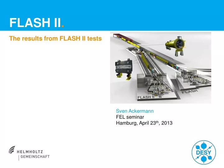
FLASH II . The results from FLASH II tests. Sven Ackermann FEL seminar Hamburg, April 23 th , 2013. Motivation for FLASH II . Generate more photon user beam time by fast switching

E N D
FLASH II. The results from FLASH II tests Sven Ackermann FEL seminar Hamburg, April23th, 2013
Motivation for FLASH II. • Generatemorephotonuser beam timeby fast switching • Variable gap undulators offer flexible, fast and easy way for wavelengthchangeslargelyindependentfromelectron beam energy • Seeding for betterphoton beam quality
FLASH II – Timing pattern (example). No RF tomodules FLASH2 250 bunches 0.3 nC Low compress. Low energy FLASH1 500 bunches 1 nC High compress. High energy RF emptying time – Bunchcharge FLASH1 – Bunchcharge FLASH2 – RF signal (e.g. Amplitude) – Kicker amplitude RF fililing time RF change time 500 µs 500 µs 250µs 98.2 ms 500 µs 50 µs t Kicker flattop Kicker rise Kicker fall 100 ms 10 Hz
Summary ofthetests. • LASER1 and LASER2 arebothfunctional • Different charges, repetitionratesandbunchnumberscouldbegenerated • LLRF dual flat top testshavebeensuccessfull • Both flat topscontrollable • Slow FB working (aslongasbunchnumberstaysthe same) • The LFF was onlyworking for a single flat top. • Usingthesecond flat top the LFF hadtobeswitched off, asitproducesharmonicswhichwontbedampedotherwise. • Opticsmismatchbetweenthe end of ACC7 and „kicker“ havebeenstudied • Simulatedgradientchangesof 50 MeV in eitherdirectiondidaffectthe SASE levelbyaround 10% to 20%. • Increaseoflosses in thecollimatormeasureable, but acceptable. • Charge dependencieswereinvestigated • The neededchanges in the RF parameters fit insidethetransistion time window
Test withtwobunchtrains (2013-01-13) • Adjustboth UV injectorlaserstothecathode • Gettransmissionwithbothlasers • Establish SASE • Change: • Energy • Compression • Charge
Startingwithbothbeamscentered on virtualcathode. LASER 1 LASER 2
Puttingbothbunchtrainsto same bunchcharge. 30 bunches 50 µs gap 20 bunches
Different compressionsarepossible Same charge!
Bothbunchtrainslasingon Ce:YAG LASER 1 only Bothlasers on thecathode LASER 2 only
SASE-spectraofbothbunchtrains LASER 1 only Bothlasers on thecathode Spectrometer was not functional due tosoftwarereasons. Thereforeonlyspectrometercameraimagesareshown LASER 2 only
Varyinggradientsofsecond flat top • Changed ACC1 and ACC39 for compression • Changedgradient in ACC4/5 for smallphotonwavelengthchanges (FLASH1 hasfixedgap undulators)
SASE-spectraofbothbunchtrains LASER 1 only Bothlasers on thecathode LASER 2 only DEbeam ~ 7 MeV (1%) Dl ~ 0.27 nm (2%)
Test withtwobunchtrains – Lessonslearned • Producedtwobunchtrainswith 30 and 20 bunches, eachlasing • Same charge, compressionandenergyledto same photon pulse energy • Different bunchcharges • Different RF settings • Lasers interchangeable • Sometoolswork on a averagingbasis, strangebehaviourshown for thebunchpatternused (30 / 50 missing / 20).
Simulation ofmismatchedoptics (2012-04-14) • Match optics in linac • Change quadstomatchhigherenergies (+/- 50 MV) • Observe SASE
Simulation ofmismatchedoptics – Lessonslearned • Mismatchedoptics for simulatedenergydeviationsbetween -50 MeVand +50 MeVwerestudied. • Energyrange was limited bythetransversecollimatoracceptance • Transmission andlasingwerealmostunaffected • Mismatchedopticsupstreamthe ECOL, for example for the different energies for FLASH1 and FLASH2 don‘tseemtobetooproblematic.
Different charges (2012-04-13) • Establish SASE • Varybunchcharge • Measurebunchlength • Measure SASE energy
Charge – SASE energydependence * Due to end ofshiftnofurtheroptimization was done ** Design performance for extractionkicker was switching time of 50 µs max.
Further tests in 2013. • Explore larger energyandphasedeviationranges for thesecond flat top. This mightbenecessary for theseedingoptionof FLASH2. • A modifiedversionofthe LFF hastobetested • Charge dependencyandbunchlengthtesthavetoberepeatedwithbothinjectorlasers • Tools havetobechecked/modified for the dual flat top operation
Thanks for yourattention! • These FLASH II testwereperformedby • S. Ackermann • V. Ayvazyan • B. Faatz • K. Klose • M. Scholz • S. Schreiber