Download
1 / 35
350 likes | 474 Vues
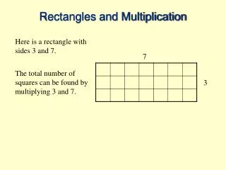
Chapter 9: Multiplication….. Saj Alam and Samya Zain. Monday November 6, 2006. 53 55 265 +265 3915. 53 10 530. Simple Multiplication Examples. 53 22 106 +106 1166. Multiplication. A B = C

E N D
Chapter 9: Multiplication…..Saj Alam and Samya Zain Monday November 6, 2006
53 • 55 265 +265 3915 • 53 • 10 530 Simple Multiplication Examples 53 • 22 106 +106 1166
Multiplication A B = C A= Multiplicand nA= Number of digits of Multiplicand (A) B = Multiplier nB= Number of digits of Multiplier (B) C = product nC nA + nB
Example 2: • 53 • 55 265 +265 3915 nA= 2 nB= 2 nC = nA + nB Example 1: • 53 nA= 2 • 10 nB= 2 530 nC= 3 nC <nA + nB nC= 4
Binary Number System • System Digits: 0 and 1 • Bit (short for binary digit): A single binary digit • LSB (least significant bit): The rightmost bit • MSB (most significant bit): The leftmost bit • 53 = 110101 • MSB LSB
= = = = = = = Binary To Decimal Conversion
MSB LSB Binary Multiplication Example 1: multiplication addition Example 2: Example 3:
Bit0 : start product 000000 110101 Bit1 : MC shifted left 53 = 110101 1101010 22 = 10110 110101 Bit2 : MC shifted left 100111110 000000 Bit3 : MC shifted left 100111110 110101 Bit4 : MC shifted left product 10010001110 Binary weight 2102928272625 2423 22 2120 1024 +128+8+4+ 2 =1166 Decimal Binary 110101 10110 53 22 106 +106 1166 = Multiplicand(MC) ; nA= 2 = Multiplier(MP) ; nB= 2 = product ; nC nA + nB
Left Shift Algorithm (LSA) Step1:Write the Multiplicand(MC) and the Multiplier(MP) with LSB lined up. Step2: Look at LSB of Multiplier. IF LSBMP = 0 put {00…nA} as initial product IF LSBMP = 1 copy Bit0 of MC as initial product Step3: Look at the next LSB bit (Bit1MP) of Multiplier. IF Bit1MP = 0 put {00…nA} as product 2 IF Bit1MP = 1 Shift left and copy Bit1 of MC as product 2 Step4:Repeat STEP 3 until all bits in the MP are used up. Step5:Check the number of digits or bits in the MC and MP. nC nA + nB
111111 1234 000000 initial product 444444 + 444444 shift right one digit 3333330 + 3777774 3777774 shift right one digit 22222200 + 25999974 25999974 shift right one digit 137110974 final product 111111000
47 = 33 = 000000 47 33 = 1551 initial product 0101111 shift right one digit 00101111 Add & shift right one digit 000101111 Add & shift right one digit 0000101111 Add & shift right one digit 1024 + 512 + +8+4+ 2+1= 1551 00000101111 Add & shift right one digit 11000001111 final product Decimal Binary 25 24 23 22 2120 Binary weight 101111 100001 = Multiplicand(MC) = Multiplier(MP) 101111 000000 000000 000000 000000 101111 211210 29 28 27 26252423222120
Right Shift Algorithm (RSA) Step1:Write the Multiplicand(MC) and the Multiplier(MP) with LSB lined up. Step2: Put initial product {000…nA} Step3a:Look at LSB of Multiplier. IF LSBMP = 0 put {00…nA} as product 2 IF LSBMP = 1 copy Bit0 of MC as product 2 Step3b: add initial product and product 2 Step3c: Shift the resulting sum one digit to right. Step4a: Look at the next LSB bit (Bit1MP) of Multiplier. IF Bit1MP = 0 put {00…nA} as product 3 IF Bit1MP = 1 copy Bit1 of MC as product 3 Step4b: add product2 and product 3 Step4c: Shift the resulting sum one digit to right. Step5: Repeat Steps 4a, 4b and 4c until all bits in the MP are used up. Step6:Check the number of digits or bits in the MC and MP. nC nA + nB
Try yourself: 111 33
Right Shift Algorithm (RSA)for 16- Bit Multiplication Wednesday November 8, 2006
CF AX BX DX CX CF AX Multiplier BX MultiplicantDX Bit count CX CF 00 00 FF FF FF FF 00 10H 16- Bit Multiplication Multiplicand = FFFF Multiplier = FFFF
AX SUB AX, AX ; AX ; CF Multiplier BX MOV BX , MPLY MultiplicantDX MOV DX, MCAND Bit count CX MOV CX, 10H ; number of bits CF Examine LSB of MPLIER RCR BX, 1 ; Examine LSB of MPLIER NEXT: Bit = 0 JNC SHIFT ; skip addition step if bit = 0 NO YES Add MCND to AX ADD AX, DX ; add MCAND to product SHIFT: Shift the product right by 1 bit. Re-examine the next bit. Decrement counter RCR AX, 1 ; shift the product 1 bit right RCR BX, 1 ; & examine next bit of MPLY DEC CX ; change counter down by 1 JCXZ DONE ; if CX = 0, all bits are done JMP NEXT ; otherwise go on to next bit Is CX = 0 ? NO DONE: YES MOV PRODL, BX ; store low word MOV PRODH, AX ; store high word RET Store final product in memory
AX SUB AX, AX ; AX ; CF Multiplicand = FF DX MOV DX, MCAND Multiplier = 3 BX MOV BX , MPLY Bit count CX MOV CX, 10H ; number of bits CF CF CF 1111 0000 0000 0000 0000 0000 AX AX AX 0000 1111 0000 0000 0000 0000 0000 0000 0000 0000 0000 0000 0000 1011 0000 0101 0000 0101 BX BX BX 0 1 DX DX DX 1111 0000 1111 0000 1111 0000 0000 1111 0000 1111 0000 1111 0000 0000 0000 0000 0000 0000 0001 0000 0001 0000 0001 0000 CX CX CX 00 03 03 16H F0 F0 0F 0F 00 RCR BX, 1 ; Examine LSB of MPLIER No change No change No change No change No change NEXT: JNC SHIFT ; skip addition step if bit = 0 ADD AX, DX ; Since CF = 1 & put in AX Note: CF is reset
SHIFT: RCR AX, 1 ; shift the product 1 bit right CF CF CF Put CF = 0 and Right shift all values 0111 1000 0111 1000 0111 1000 AX AX AX 0000 0111 0000 0111 0000 0111 1000 0000 0000 0000 1000 0000 0000 0010 0000 0101 0000 0010 BX BX BX 1 1 1 No change DX DX DX 1111 0000 1111 0000 1111 0000 0000 1111 0000 1111 0000 1111 0000 0000 0000 0000 0000 0000 0001 0000 0001 0000 0000 1111 CX CX CX No change No change RCR BX, 1 ; & examine next bit of MPLY (BX) No change No change No change 16H DEC CX ; change counter down by 1 No change No change No change 15H Note: CF did not change As CX 0 : JCXZ DONE ; if CX = 0, all bits are done JMP NEXT ; otherwise go on to next bit JNC SHIFT ; skip addition step if bit = 0 & CF = 1: ADD AX, DX
CF CF CF 0110 1000 1011 0100 0111 1000 AX AX AX 0001 0110 0000 1011 0000 0111 1000 0000 1000 0000 0100 0000 0000 0001 0000 0010 0000 0010 BX BX BX 0 1 1 No change DX DX DX 1111 0000 1111 0000 1111 0000 0000 1111 0000 1111 0000 1111 0000 0000 0000 0000 0000 0000 0000 1111 0000 1111 0000 1111 CX CX CX 0110 1000 1 0001 0110 Carry OverFlow No change No change No change SHIFT: RCR AX, 1 ; shift the product 1 bit right RCR BX, 1 ; & examine next bit of MPLY Adding: ADD result in AX: 15H 15H 15H DEC CX ; change counter down by 1 JCXZ DONE ; if CX = 0, all bits are done JMP NEXT ; otherwise go on to next bit
CF CF 1011 0100 1011 0100 AX AX 0000 1011 0000 1011 0100 0000 1010 0000 0000 0000 0000 0001 BX BX 0 1 DX DX 1111 0000 1111 0000 0000 1111 0000 1111 0000 0000 0000 0000 0000 1110 0000 1110 CX CX DEC CX ; change counter down by 1 0101 1010 0000 0101 No change No change No change No change No change 14H 14H AND SO ON untill the counter CX comes to 0H…….. As CX 0 & CF = 0: SHIFT: RCR AX, 1 ; shift the product 1 bit right RCR BX, 1 ; & examine next bit of MPLY
;*****************************************************************************;***************************************************************************** TITLE MAIN PROGRAM MUL16(UNSIGNED) ;----------------------------------------------------------------------------- ; Author: M. Sajjad Alam (University at Albany) ;----------------------------------------------------------------------------- ; This program multiplies two 16-bit numbers. The numbers to be multiplied are stored in the data segment at MPLY and MCND. Space is reserved at ; PRODL and PRODH for the product. The program multiplies unsigned numbers using the right shift algorithm. ; The largest two numbers that can be multiplied are: FFFFh and FFFFh or in decimal 65535 and 65535. For the purpose of testing the program, we suggest ; you test the program for the following examples: ;FFFFh x 10h = FFFF0h, FFFFh x 100h = FFFF00h, FFFFh x 1000h = FFFF000h ; FFFFh x Fh = EFFF1h, FFFFh x FFh = FEFF01h, FFFFh x FFFh = FFEF001h ; FFFFh x FFFFh = FFFE0001 ; INPUT: DX <- Multiplicand ; BX <- Multiplier ; CX <- Bit Counter = 10h = 16 ; OUTPUT: AX <- High word of product ; BX <- Low Word of product ;***************************************************************************** SSEG SEGMENT PARA STACK 'STACK' ; Start of Stack Segment DB 64 DUP('STACK') ; Reserve 64 bytes SSEG ENDS ; End of Stack Segment ;***************************************************************************** DSEG SEGMENT PARA PUBLIC 'DATA' ; Start of data segment ; Enter here the data words MCND DW 0FFFFH ; Store multiplicand MPLR DW 0FFFH ; Store multiplier ; Reserve two words for the product PRODL DW ? ; Low byte of Product PRODH DW ? ; High byte of Product DSEG ENDS ; End of data segment ;***************************************************************************** CSEG SEGMENT PARA PUBLIC 'CODE' ; Start of Code Segment ASSUME CS:CSEG, DS:DSEG, SS:SSEG MUL16 PROC FAR
; Set up the Stack with proper values to return to DOS or DEBUG PUSH DS ; Save DS on the stack SUB AX,AX ; Load 0 into AX PUSH AX ; Save 0 on the stack ; Initialize the Data Segment registers MOV AX,DSEG ; Store Address DSEG in AX MOV DS,AX ; Transfer AX to Data Seg Reg ;---------------------------------------------------------------------------- ; Programming task starts here START: SUB AX,AX ; Store 0 in AX and clear CF MOV BX,MPLR ; Store multiplier in BX MOV DX,MCND ; Store multiplicand in DX MOV CX,16 ; Store # of bits in CX RCR BX,1 ; Rotate BX one bit right NEXT: JNC SHIFT ; If CF=1, skip the adding ADD AX,DX ; Add multipicand to AX SHIFT: ; Perform right shift of prod RCR AX,1 ; Right shift of AX thru CF RCR BX,1 ; Right shift CF into BX DEC CX ; Decrease bit count by 1 JCXZ DONE ; Done if bit count is 0 JMP NEXT ; Otherwise loop for next bit DONE: ; Multiplication is finished MOV PRODL,BX ; Store low word at PRODL MOV PRODH,AX ; Store high word at PRODH RET ; return to debug MUL16 ENDP CSEG ENDS END MUL16
******************************************************************************************************************************** MUL16 MULTIPLICATION OF TWO 16-BIT NUMBERS Author: M. Sajjad Alam Date: November 4, 1996 Debug session showing the multiplication of 0FFh by 0FFFFh ---------------------------------------------------------------- C:\PHY353\MUL16>debug mul16_m.exe -u 1B5E:0000 1E PUSH DS 1B5E:0001 2BC0 SUB AX,AX 1B5E:0003 50 PUSH AX 1B5E:0004 B85D1B MOV AX,1B5D 1B5E:0007 8ED8 MOV DS,AX 1B5E:0009 2BC0 SUB AX,AX 1B5E:000B 8B1E0000 MOV BX,[0000] 1B5E:000F 8B160200 MOV DX,[0002] 1B5E:0013 B91000 MOV CX,0010 1B5E:0016 D1DB RCR BX,1 1B5E:0018 7302 JNB 001C 1B5E:001A 03C2 ADD AX,DX 1B5E:001C D1D8 RCR AX,1 1B5E:001E D1DB RCR BX,1 1B5E:0020 49 DEC CX 1B5E:0021 E302 JCXZ 0025 1B5E:0023 EBF3 JMP 0018 1B5E:0025 891E0400 MOV [0004],BX 1B5E:0029 A30600 MOV [0006],AX 1B5E:002C CB RETF ------------------------------------------------------------ We want to get past the point where the data segment register is loaded and the data segment is defined. At offset 0009, we have already moved the data segment offset value 1B5D into the data segment register DS. ----------------------------------------------------------------------------------------- -g9 AX=1B5D BX=0000CX=017DDX=0000 SP=013C BP=0000 SI=0000 DI=0000 DS=1B5D ES=1B39 SS=1B49 CS=1B5E IP=0009 NV UP EI PL ZR NA PE NC 1B5E:0009 2BC0 SUB AX,AX
-------------------------------------------------------------------------------------------------------------------------------------------- We can now do a dump of the data segement and identify the location of the data words corresponding to multiplicand and multiplier. ---------------------------------------------------------------------- ---------------------------------------------------------------------- Note the mulplicand 0FFFH was the first data word in the data segment and now present at location 1B5D:0000 . The multiplier 0FFH which is the second data word in the data segment is 0FFH which is equivalent to 00 FF. In the memory the lower byte FFH is loaded first, followed by the high byte 00H as can be seen at location 1B5D:0003 and 1B5D:0004, respectively. ---------------------------------------------------------------------- -dds:00 1B5D:0000 FF FF FF 00 00 00 00 00-00 00 00 00 00 00 00 00 ................ 1B5D:0010 1E 2B C0 50 B8 5D 1B 8E-D8 2B C0 8B 1E 02 00 8B .+.P.]...+...... 1B5D:0020 16 00 00 B9 10 00 D1 DB-73 02 03 C2 D1 D8 D1 DB ........s....... 1B5D:0030 49 E3 02 EB F3 89 1E 04-00 A3 06 00 CB 13 A1 06 I............... 1B5D:0040 3C 8B 16 08 3C A3 1A 41-89 16 1C 41 C6 06 B2 10 <...<..A...A.... 1B5D:0050 FF 5E 8B E5 5D C3 55 8B-EC 56 8B 5E 04 8B 76 06 .^..].U..V.^..v. 1B5D:0060 8B 04 39 07 73 06 B8 FF-FF 5E 5D C3 8B 76 06 8B ..9.s....^]..v.. 1B5D:0070 04 39 07 76 07 B8 01 00-5E 5D C3 90 2B C0 5E 5D .9.v....^]..+.^] 1B5D:0003 1B5D:0000 ---------------------------------------------------------------------- A look at the general purpose registers shows that they have data from previous operations sitting in them at this stage. ---------------------------------------------------------------------- -r AX=1B5DBX=0000CX=017DDX=0000 SP=013C BP=0000 SI=0000 DI=0000 DS=1B5D ES=1B39 SS=1B49 CS=1B5E IP=0009 NV UP EI PL ZR NA PE NC ---------------------------------------------------------------------- We will now carry on the necessary steps so that we have the registers AX, BX, CX, and DX loaded with the multiplier and multiplicand. ---------------------------------------------------------------------- 1B5E:000B 8B1E0200 MOV BX,[0002] DS:0002=00FF -t AX=0000BX=00FFCX=017DDX=0000 SP=013C BP=0000 SI=0000 DI=0000 DS=1B5D ES=1B39 SS=1B49 CS=1B5E IP=000F NV UP EI PL ZR NA PE NC 1B5E:000F 8B160000 MOV DX,[0000] DS:0000=FFFF -t AX=0000BX=00FFCX=017DDX=FFFF SP=013C BP=0000 SI=0000 DI=0000 DS=1B5D ES=1B39 SS=1B49 CS=1B5E IP=0013 NV UP EI PL ZR NA PE NC 1B5E:0013 B91000 MOV CX,0010 -t AX=0000BX=00FFCX=0010DX=FFFF SP=013C BP=0000 SI=0000 DI=0000 DS=1B5D ES=1B39 SS=1B49 CS=1B5E IP=0016 NV UP EI PL ZR NA PE NC
------------------------------------------------------------------------------------------------------------------------------------------------------------ Note: now the AX=0000, the initial product. BX contains the multiplier and DX contains the multiplicand. The register CX is loaded with the counter 10H or 16, indicating the number of shifts needed to complete the multiplication. We are now ready to shift the multiplier right into the carry bit to examine if the bit is a '1' or '0'. ------------------------------------------------------------------------------ AX=0000BX=00FFCX=0010DX=FFFF SP=013C BP=0000 SI=0000 DI=0000 DS=1B5D ES=1B39 SS=1B49 CS=1B5E IP=0016 NV UP EI PL ZR NA PE NC 1B5E:0016 D1DB RCR BX,1 -t AX=0000BX=007FCX=0010DX=FFFF SP=013C BP=0000 SI=0000 DI=0000 DS=1B5D ES=1B39 SS=1B49 CS=1B5E IP=0018 NV UP EI PL ZR NA PE CY 1B5E:0018 7302 JNB 001C ---------------------------------------------------------------------------- Note when RCR BX,1 is executed, the 1 in the LSB (least significant bit) ofregister BX is shifted to the carry flag so that is now read CY. BX now reads 007FH which is exactly what you expect if you shift 0000 0000 1111 1111right by one bit. The '0' from the 9th bit shifts into the 8th bit position,the '1' from the 5th bit position moves into the 4th bit position and the '1‘from the 1st bit moves into the carry flag. In the meantime, the 0 from the carry flag moves into the 16th bit. We have 007FH left in register BX. Note: the 1st bit of the multiplier moved into the carry flag is a'1' so we have to add the multiplicand in register DX to the intermediateproduct in AX. The instruction at offset 0018 when executed changes the next instruction counter IP to offset 001A. -------------------------------------------------------------------------- -t AX=0000BX=007FCX=0010DX=FFFF SP=013C BP=0000 SI=0000 DI=0000 DS=1B5D ES=1B39 SS=1B49 CS=1B5E IP=001A NV UP EI PL ZR NA PE CY 1B5E:001A 03C2 ADD AX,DX -t AX=FFFFBX=007FCX=0010DX=FFFF SP=013C BP=0000 SI=0000 DI=0000 DS=1B5D ES=1B39 SS=1B49 CS=1B5E IP=001C NV UP EI NG NZ NA PE NC 1B5E:001C D1D8 RCR AX,1 0000 0000 0111 1111 -------------------------------------------------------------------------- Register AX now contains the sum of the multiplicand in register DX and the initial product 0000. Note : the carry flag has been reset to NC or '0'. We are ready to shift the intermediate product right by one bit into the register BX. -------------------------------------------------------------------------- -t AX=7FFFBX=007FCX=0010DX=FFFF SP=013C BP=0000 SI=0000 DI=0000 DS=1B5D ES=1B39 SS=1B49 CS=1B5E IP=001E OV UP EI NG NZ NA PE CY When we executed RCR AX,1, the LSB of AX was moved into the carry flag, mchanging it to CY. Also note the '0' from the carry flag has been stuffed into the MSB (most significant bit) of AX so that the highest nibble in AXis 7 instead of F. Further the LSB bit of BX or the next mutliplier bit is presented into the carry flag leaving as CY or "1".
-t AX=7FFFBX=007FCX=0010DX=FFFF SP=013C BP=0000 SI=0000 DI=0000 DS=1B5D ES=1B39 SS=1B49 CS=1B5E IP=001E OV UP EI NG NZ NA PE CY 1B5E:001E D1DB RCR BX,1 ----------------------------------------------------------------- ------- When we executed RCR BX,1, the LSB of BX is shifted into the carry flag and the LSB of AX sitting in the carry flag is shifted to the highest bit of the register BX. This completes the shift of the register combination AX BX right by one bit. ----------------------------------------------------------------- ------- -t AX=7FFFBX=803FCX=0010DX=FFFF SP=013C BP=0000 SI=0000 DI=0000 DS=1B5D ES=1B39 SS=1B49 CS=1B5E IP=0020 OV UP EI NG NZ NA PE CY 1B5E:0020 49 DEC CX -------------------------------------------------------------------------- When we executed RCR BX,1, the LSB of BX is shifted into the carry flag and the LSB of AX sitting in the carry flag is shifted to the highest bit of the register BX. This completes the shift of the register combination AX BX right by one bit. ----------------------------------------------------------------- ------- -t AX=7FFFBX=803FCX=000FDX=FFFF SP=013C BP=0000 SI=0000 DI=0000 DS=1B5D ES=1B39 SS=1B49 CS=1B5E IP=0021 NV UP EI PL NZ AC PE CY 1B5E:0021 E302 JCXZ 0025 -t AX=7FFFBX=803FCX=000FDX=FFFF SP=013C BP=0000 SI=0000 DI=0000 DS=1B5D ES=1B39 SS=1B49 CS=1B5E IP=0023 NV UP EI PL NZ AC PE CY 1B5E:0023 EBF3 JMP 0018 -------------------------------------------------------------------------- We have completed examining the first bit of the multiplier so we decrease the CX counter by 1 so that CX = 000FH. Since this is not '0', the jump to end of the looping is skipped and the instruction pointer IP is set to the next location, given by offset 0018. -------------------------------------------------------------------------- -t AX=7FFFBX=803FCX=000FDX=FFFF SP=013C BP=0000 SI=0000 DI=0000 DS=1B5D ES=1B39 SS=1B49 CS=1B5E IP=0018 NV UP EI PL NZ AC PE CY 1B5E:0018 7302 JNB 001C ---------------------------------------------------------------------------- We are back at the point where are ready to check the carry flag carries a '0' or '1' from the next bit of the mutliplier in register BX. In the mean- time, the intermediate product has been shifted one bit to the right. And we are into the second loop already. We want to shorten our work, so we jump to the end of loop.
-------------------------------------------------------------------------------------------------------------------------------------------------------- We are back at the point where are ready to check the carry flag carries a '0' or '1' from the next bit of the mutliplier in register BX. In the meantime, the intermediate product has been shifted one bit to the right. And we are into the second loop already. We want to shorten our work, so we jump to the end of loop. ---------------------------------------------------------------------------- -g21 AX=BFFFBX=401FCX=000EDX=FFFF SP=013C BP=0000 SI=0000 DI=0000 DS=1B5D ES=1B39 SS=1B49 CS=1B5E IP=0021 NV UP EI PL NZ NA PO CY 1B5E:0021 E302 JCXZ 0025 -t AX=BFFFBX=401FCX=000EDX=FFFF SP=013C BP=0000 SI=0000 DI=0000 DS=1B5D ES=1B39 SS=1B49 CS=1B5E IP=0023 NV UP EI PL NZ NA PO CY 1B5E:0023 EBF3 JMP 0018 -t AX=BFFFBX=401FCX=000EDX=FFFF SP=013C BP=0000 SI=0000 DI=0000 DS=1B5D ES=1B39 SS=1B49 CS=1B5E IP=0018 NV UP EI PL NZ NA PO CY 1B5E:0018 7302 JNB 001C ---------------------------------------------------------------------------- Above, we have completed the multiplication by the second bit. The counter CX has been deceremented by 1 to 000EH. We are ready to start examining the third bit of the multiplier which is present as CY or '1'. We do not wish to demonstrate all the identical loop for the remaining bits so we wil jump to the part where multipplication by all bits have been executed. The counterCX=0 at this stage. ----------------------------------------------------------------------------
AX: 1B5D:0006 & 1B5D:0007 BX :1B5D:0004 & 1B5D:0005 -g25 AX=00FE BX=FF01 CX=0000 DX=FFFF SP=013C BP=0000 SI=0000 DI=0000 DS=1B5D ES=1B39 SS=1B49 CS=1B5E IP=0025 NV UP EI PL ZR NA PE NC 1B5E:0025 891E0400 MOV [0004],BX DS:0004=0000 -t AX=00FE BX=FF01 CX=0000 DX=FFFF SP=013C BP=0000 SI=0000 DI=0000 DS=1B5D ES=1B39 SS=1B49 CS=1B5E IP=0029 NV UP EI PL ZR NA PE NC 1B5E:0029 A30600 MOV [0006],AX DS:0006=0000 -t AX=00FE BX=FF01 CX=0000 DX=FFFF SP=013C BP=0000 SI=0000 DI=0000 DS=1B5D ES=1B39 SS=1B49 CS=1B5E IP=002C NV UP EI PL ZR NA PE NC 1B5E:002C CB RETF ---------------------------------------------------------------------------- We executed all instructions up to code offset 0025H. Here the counter CX=0signifies that 16 shifts have taken place and mutliplication by the 16 bitsin the multiplier have been completed. The product should be in registersAX BX = 00FE FF01 which is indeed what the product of FFFFH x FF should be.Below, we show where the product is stored in the data segment. The lowword of the product in register BX is loaded first at the location 1B5D:0004 and 1B5D:005 with the low byte being loaded before the higer byte.Again, the higher word of the product in register AX=00FE is loaded at location1B5D:0006 and 1B5D:007. ---------------------------------------------------------------------------- -dds:00 1B5D:0000 FF FF FF 00 01 FFFE 00-00 00 00 00 00 00 00 00 ................----------- product stored here 1B5D:0010 1E 2B C0 50 B8 5D 1B 8E-D8 2B C0 8B 1E 02 00 8B .+.P.]...+...... 1B5D:0020 16 00 00 B9 10 00 D1 DB-73 02 03 C2 D1 D8 D1 DB ........s....... 1B5D:0030 49 E3 02 EB F3 89 1E 04-00 A3 06 00 CB 0F 2B C0 I.............+. 1B5D:0040 50 57 E8 7B 93 83 C4 04-89 46 F8 EB 06 8B 5E F8 PW.{.....F....^. 1B5D:0050 C6 07 00 FF 46 F8 8B 46-F8 A3 06 3A 56 E8 D9 93 ....F..F...:V... 1B5D:0060 83 C4 02 0B C0 76 0B 56-FF 36 E0 11 E8 7B 93 83 .....v.V.6...{.. 1B5D:0070 C4 04 57 B8 19 40 50 E8-70 93 83 C4 04 B8 01 00 ..W..@P.p.......
110101 10110 000000 110101 1101010 110101 100111110 000000 100111110 110101 10010001110 53 = 22 = = Multiplicand ; MC = Multiplier ; MP Bit0 : start product 2102928272625 2423 22 2120
And Truth Table Or Truth Table Exclusive Or Truth Table
AND Gate: a logic circuit designed to compare TRUE-FALSE (or on-off or one-zero) inputs and pass a resultant TRUE signal only when all the inputs are TRUE.Binary: having two components or possible states.Binary code: a system for representing things by combinations of two symbols, such as one and zero, TRUE and FALSE, or the presence or absence of voltage.Binary number system: a number system that uses two as its base and expresses numbers as strings of zeros and ones.Bit: the smallest unit of information in a computer, equivalent to a single zero or one. The word "bit" is a contraction of binary digit.Boolean algebra: a method for expressing the logical relationships between entities such as propositions or on-off computer circuit; invented by the 19th Century English mathematician George Boole.Byte: a sequence of bits, usually eight, treated as a unit for computation or storage.Carry: the digit added to the next column in a an additional problem when the sum of the numbers in a column equals or exceeds the number base.Kilobyte: 1,024 bytes (1,024 being one K, or two to the 10th power); often used as a measure of memory capacity.Logic Gate: a circuit that accepts one or more than one input and always produces a single predicatable output.OR gate: a circuit designed to compare binary TRUE-FALSE (or on-off or one-zero) inputs and pass a resultant TRUE signal if any input is TRUE.XOR gate: a circuit designed to compare binary TRUE-FALSE (or on-off or one-zero) inputs and pass a resultant TRUE signal if a single input is TRUE, otherwise the output is FALSE. 1 Bit = Binary digit1 Byte = 8 Bits1 Kilobyte = 1,000 Bytes 1 Megabyte = 1,000 Kilobytes1 Gigabyte = 1,000 Megabytes1 Terabyte = 1,000 Gigabyte1 Pet byte = 1,000 Terabytes1 Exabyte = 1,000 Petabytes1 Zettabyte = 1,000 Exabytes1 Yottabyte = 1,000 Zettabytes