Download
1 / 12
120 likes | 300 Vues
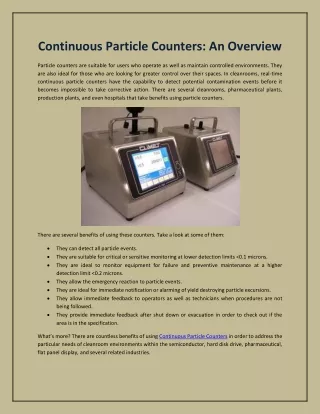
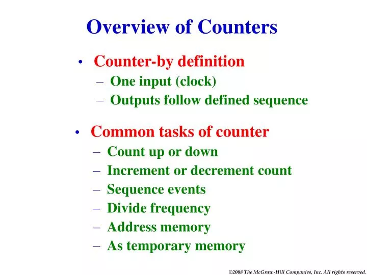
Overview of Counters. Counter-by definition One input (clock) Outputs follow defined sequence. Common tasks of counter Count up or down Increment or decrement count Sequence events Divide frequency Address memory As temporary memory. Characteristics of Counters.

E N D
Overview of Counters • Counter-by definition • One input (clock) • Outputs follow defined sequence • Common tasks of counter • Count up or down • Increment or decrement count • Sequence events • Divide frequency • Address memory • As temporary memory
Characteristics of Counters • Number of bits (4-bit, 8-bit, etc.) • Maximum count • 4 bit = 24 = 0000 to 1111 in binary • 8 bit = 28 = 0000 0000 to 1111 1111 in binary • Modulus of counter-number of states • Decade counter • 4-bit • 8-bit • Up or down counter • Asynchronous or synchronous counter • Presettable counter • Self-stopping counter
Ripple Counter Binary Output Clock Input 1 0 0 0 0 1 1 1 0 1 1 0 0 0 1 0 0 0 0 0 0 0 1 1 0 1 0 1 0 0 0 1 0 1 0 0 Pulse 5 Pulse 8 Pulse 7 Pulse 6 Pulse 4 Pulse 1 Pulse 2 Pulse 3 This 4-bit counter has 16 states and will count from binary 0000 through 1111 and then reset back to 0000. The counter has amodulus of 16. On the next clock pulse (8) all FFs will toggle because each will receive aH-to-Lpulse- one after another. Watch the count ripple thru the counter. All J-K flip-flops in the TOGGLE MODE PS and CLR inputs are INACTIVE
Clock input 1s output 2s output 4s output Ripple Counter With Waveforms Binary Output Clock Input 0 0 1 1 0 1 0 0 0 0 0 1 0 1 0 1 0 0 1 0 0 0 0 0 Pulse 5 Pulse 1 Pulse 2 Pulse 3 Pulse 4 FFs triggered on H-to-L pulse. CLK toggles 1s FF. 1s FF toggles 2s FF. 2s FF toggles 4s FF.
Short negative pulse To clear input of each FF Decade Counter Initial count at 0111 Binary Output Clock Input 1 0 0 1 0 0 0 0 0 0 0 1 0 0 1 0 0 1 1 1 0 1 0 0 0 1 0 1 1 0 0 0 0 0 1 1 Pulse 7 Pulse 6 Pulse 5 Pulse 4 Pulse 3 Pulse 2 Pulse 1 Pulse 8 All J & K inputs = 1 All PR inputs = 1 Count is at 1001. Next clock pulse will increment counter for a short time to 1010 which will activate the NAND gate and reset the counter to 0000. To change mod-16 counter to decade counter: Reset count to 0000 after 1001 (9) count. When count hits 1010 reset to 0000. See added 2-input NAND gate that clears all JK FFs to 0 when count hits 1010.
Changes from Ripple Up Counter are wiring from Q’ outputs (instead of Q outputs) to the CLK input of the next FF. Down Counter Initial count set at binary 111 1 1 1 1 1 0 1 0 1 1 0 0 0 1 1 0 1 0 Pulse 4 Pulse 2 Pulse 1 Pulse 3 Pulse 5
Self-Stopping Down Counter Watch count on Pulse 8. The count remained at binary 000. 1 1 0 1 0 0 1 0 1 1 1 1 0 0 1 0 0 0 0 1 0 0 1 1 Pulse 2 Pulse 4 Pulse 3 Pulse 1 Pulse 5 Pulse 6 Pulse 8 Pulse 7 This is a 3-bit down counter. The 1s FF is in TOGGLE mode when counting (J & K = 1). The 1s FF switches to HOLD mode when the J and K inputs are forced LOW by the OR gate when the count decrements to 000. The count stops at 000.
200 Hz Clock Input 400 Hz 100 Hz 50 Hz Counter Used for Frequency Division 4 8 2 16 800 Hz
? Hz 400 Hz ? Hz ? Hz 100 Hz 800 Hz Using the 7493 Counter IC • Counters are available in IC form. • Either ripple (7493 IC) or synchronous (74192 IC) counters are available. 1600 Hz 7493 Counter IC wired as a 4-bit binary counter
A(0) A(1) 74HC85 Magnitude Comparator A(2) A(3) A > B B(0) A = B B(1) A < B B(2) B(3) Magnitude Comparator A magnitude comparator is a combinational logic device that compares the value of two binary numbers and responds with one of three outputs (A=B or A>B or A<B). Input binary 0111 Input binary 1111 Input binary 0001 HIGH HIGH Input binary 0111 Input binary 0110 Input binary 1100 HIGH
Simple Troubleshooting Hints • Feeltop of IC to determine if it is hot • Lookfor broken connections, signs of excessive heat • Smellfor overheating • Checkpower source • Tracepath of logic through circuit • Knowthe normal operation of the circuit