Download

1 / 21
330 likes | 1.42k Vues
30 Min Culvert Design. Jered Carpenter Region 3 Roadway Design. Design Steps. Step 1) Gather hydrological & site specific data Step 2) Assume culvert size Step 3) Find headwater depth for trial size Step 4) Try another size Step 5) Compute outlet velocity

E N D
30 Min Culvert Design Jered Carpenter Region 3 Roadway Design
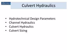
Design Steps • Step 1) Gather hydrological & site specific data • Step 2) Assume culvert size • Step 3) Find headwater depth for trial size • Step 4) Try another size • Step 5) Compute outlet velocity • Step 6) Determine Invert Protection • Step 7) Document selection
Step 1) Gather Hydrological Data Q = cia = (.35*52*.82) = 14.9 cfs Zone 6 IDF Curve Culvert Location
Step 1 Cont.) Site Specific Data • Invert In El. = 564.9’ • Invert Out El. = 564.5’ • Pipe Length = 75’ • Slope = -0.5%
Step 1 Cont.) Site Specific Data • Calculate Tail Water, TW • 2.5’ btm, class 50 rip-rap lined FBD with 2:1 side slopes @ outlet • Manning’s Equation for discharge Q = (1.486/n)*A*R2/3S1/2 • Using a spreadsheet & setting Q as a function of depth, I get the following results when d=1.7 ft: 15.0 cfs = (1.486/0.07)*10.03ft2*0.99ft2/30.051/2 • TW = 1.7’
Key #15186 – Del Rio “DR” 92+15 Jered Carpenter 11 Feb 08 1 of 1 Rational 52 Ac -0.5% Trapezoid 564.9 75 564.5 50 14.9 1.7 100 16.4 1.8
Step 2) Assume Culvert Size Start With 18” Circular CMP
Step 3) Find HW Depth For Trial Size • Assume inlet control • From Nomograph, HW/D = 3 • HW depth w/ inlet control approx. 569.4 ft., which is too high • I’ll try a 24” pipe
Step 3) Find HW Depth For Trial Size • Assume inlet control • From Nomograph, HW/D = 1.2 • HW depth w/ inlet control approx. 566.7 ft., which is OK. • The 24” pipe looks good so far
Key #15186 – Del Rio “DR” 92+15 Jered Carpenter 11 Feb 08 1 of 1 Rational 52 Ac -0.5% Trapezoid 564.9 75 564.5 50 14.9 1.7 100 16.4 1.8 CMP-Circ.-18”-Mitered 4.2 569.4 14.9 3.0 CMP-Circ.-24”-Mitered 14.9 1.2 2.4 567.3
Step 3 Continued Check for outlet control • Need to calculate H, total outlet control head loss • Outlet control nomographs can be used if outlet crown is submerged. (TW>Top of Pipe @ Outlet) • TW @1.7’ < D @ 2’ , so I will not use the nomograph
Step 3 Continued • Alternatively, H can be calculated by following the steps on the culvert design sheet • Calculate critical depth, dc • Critical depth = 1.4’ (from graph located in Chapter 8, appendix B)
Step 3 Continued • Following Steps 4 thru 5 on the culvert design sheet: • (dc+D)/2 = (1.4’+2’)/2 = 1.7’ • ho = TW or (dc+D)/2 , whichever is greater TW @ 1.7’ = (dc+D)/2 @ 1.7’ ,use 1.7’
Key #15186 – Del Rio “DR” 92+15 Jered Carpenter 11 Feb 08 1 of 1 Rational 52 Ac -0.5% Trapezoid 564.9 75 564.5 50 14.9 1.7 100 16.4 1.8 CMP-Circ.-18”-Mitered 4.2 569.4 14.9 3.0 CMP-Circ.-24”-Mitered 14.9 1.2 2.4 567.3 1.7 1.4 1.7 1.7
Step 3 Continued • Calculate Energy losses, H for the culvert From the culvert design sheet: • H = (1+ke+(29*n2*L/R1.33))*(V2/2g) Ke = .7 (from table 9-3, mitered to slope) n = .024 (from table 8-A-2) L = 75’ Use values of V and R under full flow (d=2’) R = 0.5’ V = 4.74 ft/s (Average Velocity) • H = 1.52
Step 3) Continued • Inlet Control HW Elevation = 567.3’ • Outlet Control HW Elevation = 567.9’ • The pipe flowing under outlet control.
Step 4) Try Another Size • 24” pipe is acceptable. • Remainder of the Culvert design sheet is completed.
Step 5) Compute Outlet Velocity • Previously calculated value. Determine if channel protection is required following the guidance in Chapter 11 of the hydraulics manual. Step 6) Determine Invert Protection • Follow guidance in Chapter 5 of the hydraulics manual to determine if & what type of invert protection is required.
Step 7) Document Selection Key #15186 – Del Rio “DR” 92+15 Jered Carpenter 11 Feb 08 1 of 1 Rational 52 Ac -0.5% Trapezoid 564.9 75 564.5 50 14.9 1.7 100 16.4 1.8 CMP-Circ.-18”-Mitered 4.2 569.4 14.9 3.0 CMP-Circ.-24”-Mitered 14.9 1.2 2.4 567.3 1.7 1.4 1.7 1.7 1.7 1.7 567.9 567.9 4.74 Outlet Control Trap. Channel: W=2.5’ 2:1 side slopes N= .07 (class 50 rip rap) S=0.5% Dc=1.7’ 24” Circ. Metal 0.024 Mitered