Download

1 / 56
620 likes | 713 Vues
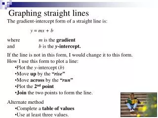
PROJECTIONS OF STRAIGHT LINES. PROJECTIONS OF STRAIGHT LINES. Definition of Straight line:. A straight line is the shortest distance between two points. Top views of two end points of a straight line, when joined, give the top view of the straight line.

E N D
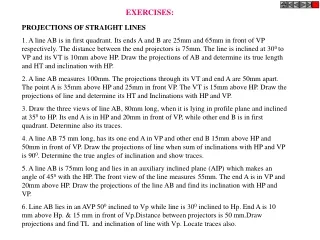
PROJECTIONS OF STRAIGHT LINES
PROJECTIONS OF STRAIGHT LINES Definition of Straight line: A straight line is the shortest distance between two points. • Top views of two end points of a straight line, when joined, give the top view of the straight line. • Front views of the two end points of a straight line, when joined, give the front view of the straight line. • Both the above projections are straight lines.
Position of Straight Line in Space • A line in space may be parallel, perpendicular or inclined to either the H.P. or V.P. or both. • It may be in one or both the reference Planes. • Line ends may be in different Quadrants. • Position of Straight Line in space can be fixed by various combinations of data like distance of its end points from reference planes, inclinations of the line with the reference planes, distance between end projectors of the line etc.
Notations used for Straight Line True length of the line: Denoted by Capital letters. e.g. AB=100 mm, means thattrue lengthof the line is 100 mm. Front View Length: Denoted by small letters. e.g. a’b’=70 mm, means thatFront View Lengthis 70 mm. Top View Length: Denoted by small letters. e.g. ab=80 mm, means thatTop View Lengthis 80 mm. Inclination of True Length of Line with H.P.: It is denoted by θ. e.g. Inclination of the line with H.P. (or Ground) is given as 300 means thatθ = 300.
Inclination of True Length of Line with V.P.: It is denoted by Φ. e.g. Inclination of the line with V.P. is given as 400 means that Φ = 400. Inclination of Front View Length with XY : It is denoted by α. e.g. Inclination of the Front View of the line with XY is given as 500 means that = 500. Inclination of Top View Length with XY : It is denoted by β. e.g. Inclination of the Top View of the line with XY is given as 300 means that β = 300. End Projector Distance: It is the distance between two projectors passing through end points of F.V. & T.V. measured parallel to XY line.
Line in Different Positions with respect to H.P. & V.P. CLASS A: Line perpendicular to (or in) one reference plane & hence parallel to both the other planes • Line perpendicular to P.P. & (hence) parallel • to both H.P. & V.P. (2) Line perpendicular to V.P. & (hence) parallel to both H.P. & P.P. (3) Line perpendicular to H.P. & (hence) parallel to both V.P. & P.P.
Line in Different Positions with respect to H.P. & V.P. CLASS B: Line parallel to (or in) one reference plane & inclined to other two planes • Line parallel to ( or in) V.P. & inclined to H.P. • by θ. (2) Line parallel to ( or in) H.P. & inclined to V.P. by . (3) Line parallel to ( or in) P.P. & inclined to H.P. by θ & V.P. by .
Line in Different Positions with respect to H.P. & V.P. CLASS C: Line inclined to all three reference planes ( Oblique lines ) Line inclined to H.P. by θ, to V.P. by and also inclined to profile plane.
Class A(1) : Line perpendicular to P.P. & hence parallel to both the other planes Y V.P. b’ a” P.P. b” a’ B Y A b X H.P. a z x .
V.P. b a Y X b’ a’ H.P. Class A(1) : Line perpendicular to P.P. & hence parallel to both the other planes
P.P. a”, b” . b’ Y1 a’ Y X b a V.P. H.P. Class A(1) : Line perpendicular to P.P. & hence parallel to both the other planes
a”, b” a’ b’ . F.V. L.H.S.V. Y1 X Y a T.V. b Class A(1) : Line perpendicular to P.P. & hence parallel to both the other planes
Exercise 1 :- A Line AB, 50mm long is perpendicular to the profile plane. The end A is 20mm below H.P. , 30mm behind V.P. & 10mm to the left of P.P. Draw the projections of straight line AB (i.e. Front View & Top View). Y1 Profile Plane Y X 20 below H.P. (2)Point A 30mm Behind V.P. Y1 Data given :- • T.L. = 50mm 50 a . . b T.V.=T.L. 30 • Line is perpendicular • to P.P. 10 • Line is 10mm left of • P.P. 20 . . b’ a’ F.V.=T.L. Scale :- 1:1
Y V.P. a’, b’ . A Y B a X H.P. b X Class A(2):Line perpendicular to V.P. & (hence) parallel to both the other Planes (i.e. H.P. & P.P.)
Class A(2):Line perpendicular to V.P. & (hence) parallel to both the other Planes V.P. a’, b’ Y a X H.P. b .
Class A(2):Line perpendicular to V.P. & (hence) parallel to both the other Planes V.P. a’, b’ . F.V. Y X a T.V. b H.P.
Exercise 2 :- A Line ABC, 80mm long is perpendicular to V.P & 50mm below H.P. Point B, 20mm from A is on V.P. A is in 4th quadrant. Draw the projections of line ABC. Y X . Data given :- c • T.L. = 80mm (2) AB = 20, BC = 60 60 (3) Point B is in V.P. . b • Line is 50mm below H.P. 20 . 50 - Point A is in 4th quadrant a . a’,b’,c’ - Line is perpendicular to V.P. Scale :- 1:1
Y V.P. b’ B Y a’ A . X H.P. a,b X Class A(3):Line perpendicular to H.P. & (hence) parallel to both the other Planes
V.P. b’ Y a’ X . a,b H.P. Class A(3):Line perpendicular to H.P. & (hence) parallel to both the other Planes
V.P. a’ b’ Y X . a, b H.P. Class A(3):Line perpendicular to H.P. & (hence) parallel to both the other Planes
Exercise 3:- A Line AB, 50mm long is perpendicular to H.P. & it is below H.P. Point A is on H.P. & 30mm behind V.P. Draw the projections of the line AB. X Y On H.P. (2) Point A 30mm Behind V.P. Data given:- . a,b • T.L. = 50mm 30 . a’ (3) Line is perpendicular to H.P. F.V.=T.L. 50 b’ . Scale :- 1:1
Class B(1): Line contained by ( or parallel to) V.P. & inclined to H.P. by Y V.P. B b’ Y Ө b A a’ a X H.P. X
Class B(1): Line contained by ( or parallel to) V.P. & inclined to H.P. by V.P. b’ Y Ө b a’ a X H.P.
Class B(1): Line contained by ( or parallel to) V.P. & inclined to H.P. by V.P. b’ a’ a b Ө Y X V.P.
Exercise 4 :- A Line AB, 75mm long, is in V.P. It makes an angle of 300 with the H.P. Point A is 20mm above H.P. Draw the projections of line AB. X Y b’ Data given :- F.V.=T.L. • T.L. = 75mm (2) = 300 . ==30º a’ (3)Point A = 20mm above H.P. 20 . b a T.V. - Line AB is in V.P. Scale :- 1:1
Class B(2) : Line parallel to (or contained by) H.P. & inclined to V.P. by V.P. V.P. Y b’ a’ A B Y X Y H.P. X X H.P. b’ a’ ø a b a = b
Exercise 5 :- A Line AB, 120mm long, is parallel to H.P. and inclined to V.P. by 500. Point B is 10mm above H.P. and 40mm on in front of V.P. Point A is behind V.P. Draw the projection of line AB. X Y 10 above H.P. (3) Point B 40mm in Front of V.P. Data given :- . a • T.L. = 120mm . . b’ F.V. (2) = 500 a’ 10 = P.L. = T.L 40 - Line is parallel to H.P. . • Point A is behind V.P. b Scale :- 1:1
Class C:Line inclined to H.P. by & V.P. by ( i.e. Line inclined to both the planes) Y V.P. b’ B Y a’ A X a H.P. b X
Class C:Line inclined to H.P. by & V.P. by ( i.e. Line inclined to both the planes) V.P. b’ Y a’ X a b H.P.
Class C:Line inclined to H.P. by & V.P. by ( i.e. Line inclined to both the planes) V.P. b’ a’ X Y a b H.P.
Exercise 6:- A Line AB, 90 mm long, is inclined to H.P. by 300and inclined to V.P. by 450. The line is in first quadrant with Point A 15 mm above H.P. and 25 mm in front of V.P. Draw the projection of line AB. Locus of b’ α θ 15 above H.P. Y (4) Point A X 25 mm in Front of V.P. Φ β Locus of b b1’ b’ Data Given :- (1) T.L.=90 mm T.L.= 90 F.V. (2) Θ =300 . a’ (3) Φ =450 b2’ 15 . 25 b1 a Answers :- (1) F.V.= 64 mm T.V. (2) T.V = 78 mm (4) = 550 (3) = 450 b2 b
Exercise 7 :- The distance between the end projectors of a straight line AB is 80mm. Point A is 10mm above H.P. and 30mm in front of V.P. Point B is 40mm above H.P. and 50mm behind V.P. Draw the projections and find the inclination of straight line AB with H.P & V.P. and the true length of the line. 10 above H.P. (2) Point A Locus of b 30mm in front of V.P. Locus of b’ (3) Point B 40 above H.P. 50mm behind V.P. Y X Data given :- • E.P.D. = 80mm . b b1 . b’ b2’ F.V. 50 . 40 b1’ Answers :- a’ 10 150 (1) = T.V. . 30 (2) = 430 a b2 117mm (3) T.L. = 80
Exersice 8 :A room is 5m X 4.5m X 4 m high. Determine by method of projections of straight lines, distance between diagonally(solid) opposite corners of the room. Locus of b’ b’ . B H . θ A a’ Y X a L W b X Data Given :- b2’ (1) Length of the room=L=5m (2) Breadth of the room=B=4.5m H (3) Height of the room=H=4m a’b2’= 7.826m b2 B L Scale :- 1:100
Exercise 9 : The F.V. of a line MN, 90 mm long, measures 65 mm and makes 450 with XY. Point M is in V.P. and 20 mm below H.P. Point N is in the first quadrant. Draw the projections and find inclinations of line with H.P. and V.P. Locus of n’ 20mm below H.P. (1) Point M In V.P. X Y Φ θ α Locus of n Data Given: n1’ n’ (2) T.L.= 90 mm . F.V. n1 m (3) F.V.= 65 mm (4) α = 450 20 . (5) Point N is in first Quadrant n2’ m’ Answers: T.V. (1) Θ = 310 (2) Φ = 440 n2 n Scale:- 1:1
Class B(3): Line parallel to (or contained by) P.P., inclined to H.P. by & to V.P. by Y V.P. P.P. A Y H.P. B X X Z a” a’ b” b’ a b
Class B(3): Line parallel to (or contained by) P.P., inclined to H.P. by & to V.P. by P.P. V.P. a” b” X Y H.P. a’ b’ a b
Exercise 10 :- The distance between the end projectors of line MN is zero. Point M is 40 mm below H.P. & 25 mm behind V.P. Point N is 15 mm below H.P. & 65 mm behind V.P. Draw its projections and find the angle of the line with H.P. and V.P. Also find the true length of the line. 40 below H.P. 15 below H.P. (1) Point M (2) Point N 25 mm behind V.P. 65 mm behind V.P. 450 Y X Data given :- . n T.V. . m 65 25 (3) End projector dist. = 0 . . 15 n’ n” 40 F.V. . . T.L. m’ m”
TRACES OF A LINE Definition:When a line is inclined to a plane, it will meet that plane, produced if necessary. The point where the line or line producedmeets the planeis calledtrace. Horizontal Trace:The point of intersection of the inclined line with the H.P. is calledHorizontal Traceor simplyH.T. Vertical Trace:The point of intersection of the inclined line with the V.P. is calledVertical Traceor simplyV.T.
V.P. b’ Y B a’ A b H.P. a X H.T. V.T. V.P. Example to illustrate the concept of traces F.V. . h v T.V. .
IMPORTANT POINTS REGARDING TRACES OF A LINE - If a line is inclined to both H.P. & V.P. then its Front view, h’ and V.T. must be on the same straight line. e.g. if front view of a line AB is a’b’, then h,a’,b’ and V.T. must be on a same straight line. - If a line is inclined to both H.P. & V.P. then its Top view, v and H.T. must be on the same straight line. e.g. if Top View of a line AB is ab, then v, a, b and H.T. must be on a same straight line.
V.P. a’, b’ . A V.T. Y B a H.P. b IMPORTANT POINTS REGARDING TRACES OF A LINE (1) If a line is parallel to any of the plane, it has no trace upon that plane. e.g. If the line is parallel to horizontal plane then that line will not meet H.P and hence there will be no H.T. and only V.T.
A B b’ V.T. . a’ ø a b IMPORTANT POINTS REGARDING TRACES OF A LINE (1) If a line is parallel to any of the plane, it has no trace upon that plane. e.g. If the line is parallel to horizontal plane then that line will not meet H.P and hence there will be no H.T. and only V.T.
V.P. b’ B Y a’ A . X H.P. a,b H.T. IMPORTANT POINTS REGARDING TRACES OF A LINE e.g. If the line is parallel to Vertical Plane then that line will not meet V.P and hence there will be no V.T. and only H.T.
b’ F.V.=T.L. = =300 a’ 20 h’ b a T.V. H.T. IMPORTANT POINTS REGARDING TRACES OF A LINE e.g. If the line is parallel to Vertical Plane then that line will not meet V.P and hence there will be no V.T. and only H.T.
Exercise 11 : A line AB, 80 mm long is seen as a straight line of length 55mm in its front view and of length 65 mm in its top view. Its end A is 10 mm above H.P. & is in first quadrant where as end B is 25 mm behind V.P. and is in Second Quadrant. Draw its projections and find out its inclinations with H.P. & V.P. and also locate its traces.
Data Given: 10 mm above H.P. (4) End A ??? I.F.O V.P. Locus of b’ ??? above H.P. (5) End B 25mm behind V.P. Locus of b X Y (1) T.L.=80 mm (2) F.V. = 55mm (3) T.V. = 65mm b1’ b’ . V.T. F.V. b2 b Answers: (1) = 360 25 a’ b2’ 10 (2) = 460 v h (3) H.T.=46mm I.F.O. V.P. T.V. a . (4) V.T.=36mm above H.P. 65 b1 H.T.
Exercise 12 :- Two Mangoes on a tree, planted near the compound wall of a bunglow, are 1m and 1.25m above the ground and 0.5m & 0.75m from a 15cm thick compound wall but on the opposite sides of it. The distance between Mangoes measured along the ground and parallel to the wall is 1m. Determine the real distance between centres of two mangoes. Y X Locus of q’ 1m above ground 15cm (2) Point P 0.5 behind wall 1.25m above ground (3) Point Q 0.75m in front of wall Locus of q G L Data Given :- q2 p (1) E.P.D. = 1m 0.5m T.V. q2’ q’ 0.75m F.V. p’ (4) Wall thickness = 15cm q Scale :- 1:20 1.25m Answer :- 1m - the real distance between centres of two mangoes = p’q2’= 1.63m 1m
Exercise 13 : A divider instrument of a compass box having two equal arms AB & BC hinged at B is kept in H.P. on its needle point A & C with the line joining A & C is perpendicular to V.P. It is seen in front view as a straight line 100mm long inclined at 300 to H.P. while it is seen in top view as an angle abc with <abc = 600. Draw its front view and top view and find; • The height of point B above H.P. • The apart distance between the needle points • A & C • (3)The lengths of arms AB & BC with real • between them
Locus of b’ α X Y 2 600 Locus of b’ Data Given: b’ f (1) F.V.=100 mm F.V. H (2) α = 300 (3) <abc =2 = 60° a’,c’ b1’ (4) ac is perpendicular to V.P. a,A Answers: (1) AB = 112mm AB dist. b (2) 2 = 530 b1, B (3) AC = 100 mm c,C