Download
1 / 6
60 likes | 239 Vues
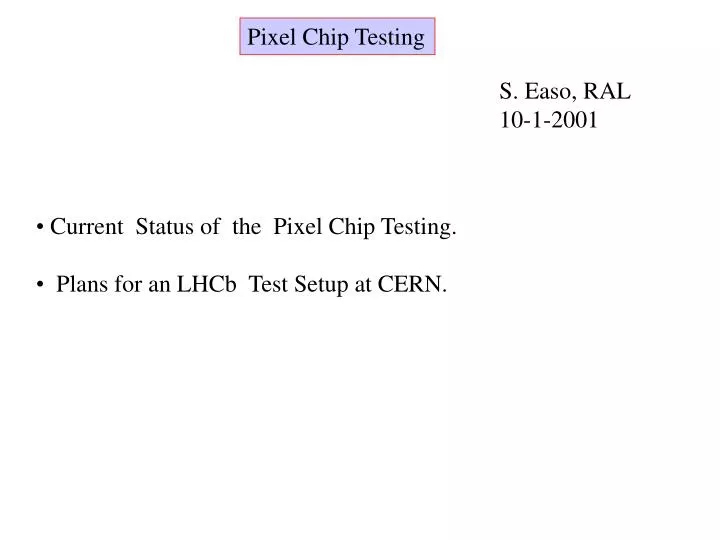
Pixel Chip Testing. S. Easo, RAL 10-1-2001. Current Status of the Pixel Chip Testing. Plans for an LHCb Test Setup at CERN. Current Status. On the IC tester the chip is proved to be functional. This setup is mostly software controlled. The only

E N D
Pixel Chip Testing S. Easo, RAL 10-1-2001 • Current Status of the Pixel Chip Testing. • Plans for an LHCb Test Setup at CERN.
Current Status • On the IC tester the chip is proved to be functional. • This setup is mostly software controlled. The only • external hardware needed is the pixel chip glued and • bonded on a board and a couple of power supplies. • IC tester is in high demand at CERN; • Not suitable for high statistics tests. • For detailed chip characterization another Test Setup is used: • A Test Setup using VME is working in ALICE. • This uses different boards which are custom made • within the CERN-ALICE group. • I am copying this setup and its software for LHCb.
Current Pixel Test Setup VME PC P I L o T M X I JTAG Controller Con- figu- ration Fast Controls Data Power Supplies Readout Interface +5V,-5V analogue, +5V digital Board to which the Pixel chip is glued and Bonded. Pixel Chip
Pixel Test Setup • Pilot Board: • Provides the Fast Control Signals. • Examples: (1) Strobe ( first level trigger) is a signal to • write data to the pixel chip FIFOS. • (2) Next Event Read is a signal to • read data from pixel chip FIFOs. • (3) Test_Pulse: To trigger the injection of test charge • into pixel preamplifiers. • Acquires Data and performs zero suppression. • Current version works at 10 MHz. It can be modified to 40 MHz. • Readout Interface Board (from Mike Burns): • Provides Power, Analogue bias etc. • Converts LVDS <---->GTL . Pixel chip uses GTL. • Is expected to be replaced by the PIXIE board in the future, • for testing the pixel chip on carriers and tubes.
Pixel Test Setup • JTAG Controller: • Commercially produced board. • Used for the slow controls: Setup Thresholds, Configuration etc. • ALICE uses a version mounted on the VME crate. I use the • PC version since it is the only one available for now. • This controller is verified to be functional, during last month. Data path: Pixel Chip-->Readout Interface-->Pilot board-->PC. Readout Software: Labview for now. Can be translated in the future. Example of Measurement: ‘S’ curve to estimate the noise and threshold of Pixel channels.
Plans and Summary • For the LHCb setup, all components except the Readout Interface • Board are available. This board is undergoing tests and is • expected to be available in a few days. • I plan to write the software needed for the characterization of the • chips and perform the characterization on the bare chips glued • on the board. • This setup is expected to be a prototype for LHCb specific • tests on the chip. We should be able to use this, to test • chips mounted on carriers, tubes etc. Once functional, we can • copy this setup for large scale HPD testing.