Download
1 / 27
270 likes | 445 Vues
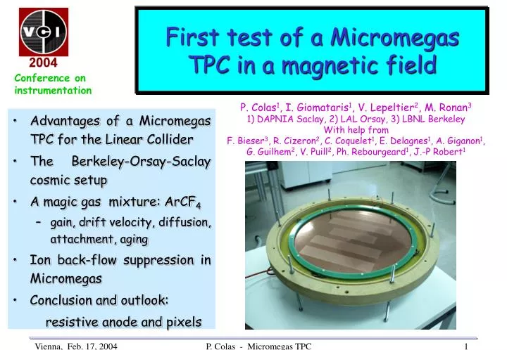
First test of a Micromegas TPC in a magnetic field. Conference on instrumentation. P. Colas 1 , I. Giomataris 1 , V. Lepeltier 2 , M. Ronan 3 1) DAPNIA Saclay, 2) LAL Orsay, 3) LBNL Berkeley With help from F. Bieser 3 , R. Cizeron 2 , C. Coquelet 1 , E. Delagnes 1 , A. Giganon 1 ,

E N D
First test of a Micromegas TPC in a magnetic field Conference on instrumentation P. Colas1, I. Giomataris1, V. Lepeltier2, M. Ronan3 1) DAPNIA Saclay, 2) LAL Orsay, 3) LBNL Berkeley With help from F. Bieser3, R. Cizeron2, C. Coquelet1, E. Delagnes1, A. Giganon1, G. Guilhem2, V. Puill2, Ph. Rebourgeard1, J.-P Robert1 • Advantages of a Micromegas TPC for the Linear Collider • The Berkeley-Orsay-Saclay cosmic setup • A magic gas mixture: ArCF4 • gain, drift velocity, diffusion, attachment, aging • Ion back-flow suppression in Micromegas • Conclusion and outlook: resistive anode and pixels P. Colas - Micromegas TPC
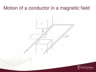
A LARGE TPC FOR THE LINEAR COLLIDER The tracker of the LC detector should be a TPC with - good 2-track separation (<8mm) - 10 times better momentum resolution than at LEP - low ion back-flow - possibility to operate with a H-less gas (200 n/BX) - High B field (4T) to wipe out the (large) background We proposed a Micromegas readout to fulfill these requirements (see also J. Kaminski et al.’s poster P.A9 for the GEM TPC) Using recent measurements, simulations and recently re-analysed data, we show that all the requirements can be met. P. Colas - Micromegas TPC
2x10 mm2 pads 1x10 mm2 pads THE BERKELEY-ORSAY-SACLAY COSMIC-RAY SETUP 50 cm drift length, 50 cm diameter 1024 channels The largest Micropattern TPC ever built Field cage Detector Front end electronics In operation since July 2003 Data taking with field in Nov. 2003 P. Colas - Micromegas TPC
2T magnet in Saclay Field cage assembly in Orsay P. Colas - Micromegas TPC
Electronics and Data Acquisition From the STAR TPC (from Berkeley) 1024 readout channels with pre-amplification, shaping, 20 MHz sampling over 10 bit ADC. VME-based DAQ. Very steady data taking conditions, with mesh currents below 0.3 nA and essentially no sparking. Trigger rate 2.5 Hz. DAQ rate 0.1 Hz. Display and reconstruction using Java code from Dean Karlen, adapted by Mike Ronan. Java-based analysis (JAS3 and AIDA) P. Colas - Micromegas TPC
P10, Vmesh = 356 V P. Colas - Micromegas TPC
Data have been taken with the following gas mixtures: Ar-CH4 10% (v = 5cm/ms @ 120 V/cm) Ar-Isobutane 5% (v = 4.15 cm/ms @ 200 V/cm) Ar-CF4 3% (v = 8.6 cm/ms @ 200 V/cm) Hit total amplitude (ADC counts) Mainly few-GeV muons: minimum-ionizing and low multiple scattering Curvature 1/R (mm-1) P. Colas - Micromegas TPC
Ar CF4: a ‘magic gas’ for the Micromegas TPC Introduction: choosing a gas mixture for the TPC R1) Have enough primary electrons R2) Have a velocity plateau at low enough voltage (<200 V/cm -> 50 kV for 2.5m) R3) Keep cost reasonable (large volume) -> Requirements 1 to 3 point to Argon as carrier gas R4) Avoid Hydrogen (200 n/bx at TESLA) -> CO2 too slow, needs too high a field. ->ArCF4 OK, but attachment? Aging? Reactivity? => USE MEASUREMENTS (June 2002, Nov. 2003) AND SIMULATIONS (Magboltz by S. Biagi) P. Colas - Micromegas TPC
Ar CF4: drift velocity tmax = (103+-3) x 50ns First 15 buckets used for ped. calculation Measurement of the drift velocity in Ar:CF4(97:3) at E=200 V/cm 5150 ns + 200 ns (trigger delay) for 47.9 cm drift: V = 9.0 +- 0.3 cm/ms consistent with Magboltz (by S. Biagi) 8.6 cm/ms. Cross-check: for Ar:isobutane (95:5) we find v = 4.2+-0.1cm/ms Magboltz: 4.15 cm/ms P. Colas - Micromegas TPC
Ar CF4: gain Measurements using a simple device with a 25 MBq 55Fe source (April 2002). Note hyperexponential, but stable, behaviour at high voltage In the cosmic data taking Micromegas was operated at a gain of about 2000. (50 micron gap with 350 V) Ar CF4: aging CF4 known to be aggressive to some materials. However: - no sign of aging after months of operation with various detectors/mixtures -X-ray aging test performed (20 l/h Ar+5%CF4): 2 mC/mm2 = 13000 years of LC P. Colas - Micromegas TPC
Ar CF4: attachment Fear: there exists an attachment resonance in CF4 (narrow but present) Attachment coefficient must be << 0.01 cm-1 for a 2.5 m TPC MC predicts : -No attachmt in the drift region (E<400 V/cm) -attachmt overwhelmed by Townsend in the amplification region (E>10kV/cm) P. Colas - Micromegas TPC
Ar CF4: attachment Measurement with a d=1.29 cm drift setup. Measure signal amplitude from a focused laser (June 2002) . I=I0 exp(-ad) -> Magboltz reliable Measurement with the cosmic setup: Exponential fit to the mean signal vs distance gives the limit: Attachment < 4.1 10-3 cm-1 @ 90% C.L. -> OK for a large TPC Truncated mean signal vs drift time P. Colas - Micromegas TPC
Ar CF4: diffusion At 200 V/cm, for Ar+3%CF4, Monte Carlo predicts Dz = 240 mm/cm => 2.5 mm 2-track resolution in z at 1 meter => 250 mm z hit resolution at 1 meter Dt(B=0) = 350 mm/cm Dt(B) = Dt(B=0)/(1+w2t2), w=eB/me wt = 4.5 at 1T => expect 75 mm/cm) for B=1T P. Colas - Micromegas TPC
Ar CF4: transverse diffusion Measurement in the cosmic setup : Compute the rms width of hits for each track Plot sx2as a function of the drift time fit to a straight line Obtain the transverse diffusion constant at B=1T: Dt = 64+-13 mm/cm Consistent with expectation of 75 mm. sx2 (mm2) Drift distance (cm) P. Colas - Micromegas TPC
Potential point resolution Extrapolate to B=4T (wt=18) Dt = 15 mm/cm => track width = 150 mm at 1 m For 1cm long pads (100 electrons) : potential resolution of 15 mm at 1m ! But this would require O(200mm)-wide pads: too many channels (but good for microTPC). Two ways out: => spread the charge after amplification (resistive anode for instance) => go to digital pixels (300x300 microns have been shown to be optimal by M. Hauschild) Ar-CF4 3%, Vmesh = 340 VB = 1 Tesla wt ~ 4.5 P. Colas - Micromegas TPC
Position sensing from charge dispersion in micropattern gas detectors with a resistive anode (Dixit et al.) or Micromegas P. Colas - Micromegas TPC
microMegas orMicromegas GEM & Micromegas Tests at Carleton • Resistive anode spreads the avalanche cluster charge • Position obtained from centroid of dispersed charge sampled by several pads • In contrast to the GEM, in Micromegas there is little transverse diffusion after gain which makes centroid determination difficult • resistive foil C-loaded Kapton Carbon loaded Kapton ~ 0.5 MW/o Thickness ~ 30 m Amplification withGEM P. Colas - Micromegas TPC
Micromegas TPC Resolution with 2mm pads Collaboration with Carleton Univ., Ottawa (M. Dixit, K. Sachs, et al.) Pad response function width from charge dispersion on resistive anode X-ray spot position 15.35 mm Pad edges @ 15 mm and 17 mm Centre @ 16 mm Measured spatial resolution :68 mm P. Colas - Micromegas TPC
Micromegas gain with a resistive anode Argon/Isobutane 90/10 Resistive anode suppresses sparking, stabilizing Micromegas P. Colas - Micromegas TPC
First data from a Micromegas+pixel detector see also poster P.B22 Harry van der Graaf, Alessandro Fornaini, Jan Timmermans, Jan Visschers (NIKHEF Amsterdam) Paul Colas, Y. Giomataris (DAPNIA Saclay)Erik Heijne (CERN/MEDIPIX2) Jurriaan Schmitz (Univ. Twente/MESA) Medipix2 CMOS chip in 0.25mm technology with 65000 55x55 mm2 Si pixels, noise about 200e-/channel After an amplification stage by a Micromegas (Ar+5% isobutane) Smallest Micromegas ever built P. Colas - Micromegas TPC
First data from a Micromegas+pixel detector Feb. 13, ‘04 MICROMEGAS Clear signal from an iron 55 source (220 e- per photon) 300mx500m clouds as expected 15 mm drift GAIN=700 55Fe, 1s No source, 1s 55Fe, 10s 3-GEM device already saw particles (March ’03, Feb. ’04) Larger spread (O(1mm)) due to mm-thick gaps with kV/cm fields 100 mm drift GAIN = 40 000 MICROMEGAS + PIXELS :very promising device + powerful tool for studying Micromegas 55Fe, 2s GEM P. Colas - Micromegas TPC
6 and 3 keV photons as seen by a Micromegas+Medipix2 detector 400m 500m P. Colas - Micromegas TPC
Stability of operation of Micromegas in a magnetic field B=1 tesla 15 cm TPC Stability of the position and width of the 55Fe peak as a function of the field P. Colas - Micromegas TPC
Natural limitation of the ion back-flow See V. Lepeltier’s poster, P.C13 S1/S2 ~ Eamplif / Edrift Electrons suffer diffusion (s=12mm in the 50mm gap) -> spread over distances comparable to the grid pitch l=25-50mm Ions follow field lines, most of them return to the grid, as the ratio amplification field / drift field is large If s/l >0.5, the fraction of back-flowing ions is 1/(field ratio) S1 S2 In Micromegas, the ion back flow is suppressed by O(10-3) For gains of 500-1000, this is not more than the primary ionisation In the test, the gain was 310. Data from dec 2001, reanalysed. P. Colas - Micromegas TPC
Optimal case (reached for a 1000 lpi grid) Good understanding and stability of the ion feedback : need for manufacturing large grids at the 25 micron pitch. P. Colas - Micromegas TPC
Conclusions • A large TPC read out by Micromegas is now in operation in a 2T magnet. • Experimental tests and Monte Carlo studies allowed us to limit the choice of gas mixtures for Micromegas. Ar-CF4 is one of the favorite with possibly an isobutane or CO2 admixture. • Theoretical and experimental studies have demonstrated that the ion feedback can be suppressed down to the 3 permil level. • Tests with simple dedicated setups have proven the principle of operation and shown that the performances of Micromegas hold in a magnetic field (March 2002, June 2002 and January 2003 data taking) P. Colas - Micromegas TPC
Outlook • The position resolution issue at an affordable cost has to be addressed. There exists at least two possibilities: • Pixel readout • Spread the charge after gain (resistive anode coating for instance) • For both, the «proof of principle» has been done P. Colas - Micromegas TPC