Download

1 / 26
260 likes | 383 Vues
Tracking. Canada A.Bellerive, K.Boudjemline, J.Miyamato, Carleton University E.Neuheimer, E.Rollin, K.Sachs &Y.Shin J.-P. Martin University of Montreal France D.Burke, P.Colas, A.Giganon & I.Giomataris DAPNIA CEA Saclay V.Lepeltier & Th.Zerguerras LAL Orsay

E N D
Tracking Canada A.Bellerive, K.Boudjemline, J.Miyamato, Carleton UniversityE.Neuheimer, E.Rollin, K.Sachs &Y.Shin J.-P. MartinUniversity of Montreal FranceD.Burke, P.Colas, A.Giganon & I.GiomatarisDAPNIA CEA Saclay V.Lepeltier & Th.ZerguerrasLAL Orsay GermanyR. SettlesMPI (Munich) JapanH.Kuroiwa & T.TakahashiHiroshima University K.Fujii, M.Kobayashi, T.Matsuda & H.YamaokaKEK/IPNS Y.KatoKinnki University T.WatanabeKogakuin University T.Araki, H.Fujishima, T.Higashi, , K.Kodomatsu,Saga UniversityA.Sugiyama, T.Yamamoto &Y.TanakaA.YamaguchiTsukuba UniversityM.Habu, S.Matsushita, K.Nakamura & O.NitoTokyo University of Agriculture &Technology Test beam performance of MPGD-TPC readout concept of charge dispersion in a magnetic field Madhu Dixit Carleton University & TRIUMF
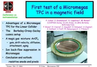
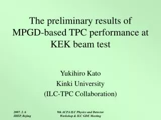
Motivation & overview • ILC tracker goal (1/pT) ≤ 5.10-5 (GeV/c)-1=> MPGD-TPC ∆(1/pT) ≤ 1.5 x 10⁻⁴ (GeV/c)-1 • TDR TPC: 200 pads; Tr ~ 100 m ( 2 m drift), pad size 2 x 6 mm2=> Total TPC pad count ~1.5 x 10⁶ • R&D shows 2 mm too wide for 100 m resolution with normal readout. Ways to improve the MPGD-TPC resolution: • Under consideration - narrower 1 mm x 6 mm pads (3 x 10⁶ total). R&D issues: High density electronics, increased heat load, TPC endcap mass etc. • Alternative: Disperse avalanche charge to improve resolution for wide pads. Development of a TPC readout with charge dispersion in MPGDs with a resistive anode. • Charge dispersion demonstrated in cosmic ray TPC tests with no magnet. • International collaboration to test the concept in a magnet. • 1 T superconducting magnet & 4 GeV/c hadron test beam at KEK PS. • Two TPCs: Multi Technology Test TPC - MT3 TPC (MPI Munich) + Carleton TPCwithMicromegas (Saclay) & GEMs(Saga University). • Two weeks of beam data in October2005. • First results on magnetic field performance of MPGD-TPC with charge dispersion readout in a test beam reported here. LCWS Bangalore 2006
TPC resolution should only be limited by transverse diffusion • The physics limit of TPC resolution comes from transverse diffusion: Neff = effective electron statistics. • For best resolution, choose a gas with smallest diffusion.Applicable to the wire TPC which uses induced cathode pad signals for position determination. Main factors limiting wire TPC resolution are the ExB & track angle systematic effects. • There is no ExB effect to limit the MPGD-TPC. But also no induced pad signals for precise position determination. The MPGD-TPC resolution is limited by pad width & gets worse for smaller diffusion. Charge dispersion - a pad signal induction mechanism to make position determination insensitive to pad width. LCWS Bangalore 2006
Proportionalwire Micro PatternGas Detector Anode pads Cathode pads width w width w Direct signal on the MPGD anode pad Induced cathode signal determined by geometry Pad width limits the MPGD-TPC resolutionExB angle effects limit the wire/pad TPC resolution For small diffusion, less precise centroid for wide pads Accurate centroid determination possible with wide pads Gain fluctuations affect Neff, the effective number of electrons. Neff <N> (average no. of electrons) ~ 1/<1/N> LCWS Bangalore 2006
Charge dispersion in a MPGD with a resistive anode Modified MPGD anode with a high resistivity film bonded to a readout plane with an insulating spacer. 2-dimensional continuous RC network defined by material properties & geometry. Point charge at r = 0 & t = 0 disperses with time. Time dependent anode charge density sampled by readout pads. Equation for surface charge density function on the 2-dim. continuous RC network: (r) Q (r,t) integral over pads mm ns r / mm LCWS Bangalore 2006
Al-Si Cermet on mylar Drift Gap MESH Amplification Gap 50 m pillars Micromegas with a resistive anode for the charge dispersion readout LCWS Bangalore 2006
The two beam test TPCs Carleton TPC MT3 TPC Micromegas Charge dispersion readout endplate - Micromegas 10 x10 cm2 - Drift distance: 16 cm - 126 pads, 2 x 6 mm2 each in 7 rows • ALEPH preamps + 200 MHz FADCs rebinned to 25 MHz equivalent FADCs • Micromegas & GEMs 10 x10 cm2 • Drift distance 25.9 cm - 384 pads 2.3 x 6.3 mm2 each in 16 rows • ALEPH preamps + 11 MHz AlephTime Projection Digitizers LCWS Bangalore 2006
KEK PS 2 test beam set up with Carleton & MT3 TPCsBeam data taken both in & outside the magnet for the two TPCs 4 GeV/c hadrons (mostlyπs) 0.5 & 1 GeV/c electrons Super conducting 1.2 T magnet without return yoke Inner diameter : 850 mm Effective length: 1 m Carleton TPC in the beam outside the magnet LCWS Bangalore 2006
The pad response function (PRF) • PRF - a measure of pad signal as a function of track position. • PRF determined empirically from track data itself. • PRF parameterization: • Parameters functions of FWHM & the base width. • Position determined from the PRF fit has bias. • The bias correction is determined from calibration. LCWS Bangalore 2006
spreading of charge due to foil can be seen across six pads MT3 TPC event display + Micromegas read out with Aleph TPDs 2.3 x 6.3 mm2 pads Ar+5%iC4H10 E=220V/cmDTr=193µm/cm @ B= 1T Example pad response function Data analysis is in progress LCWS Bangalore 2006
Track display -Ar+5%iC4H10Micromegas 2 x 6 mm2 pads B = 1 T Zdrift = 15.3 cm main pulse LCWS Bangalore 2006
6 mm [ ] 2 2 = 2 mm rows i=pads Track fit using the the PRF Track at: xtrack= x0+ tan() yrow Determine x0 & by minimizing2 for the entire event One parameter fit for xrow (track position for a given row) using Bias = Mean of residuals (xrow-xtrack)as a function of xtrack Resolution = of track residuals LCWS Bangalore 2006
Pad Response Function / Ar+5%iC4H10Micromegas+Carleton TPC 2 x 6 mm2 pads, B = 1 T 30 z regions / 0.5 cm step 0 < z < 0.5 cm 0 .5 < z < 1 cm 1 < z < 1.5 cm 1.5 < z < 2 cm 2 < z < 2.5 cm 2.5 < z < 3 cm 3 < z < 3.5 cm 3.5 < z < 4 cm 4 < z < 4.5 cm 4.5 < z < 5 cm 5 < z < 5.5 cm 5.5 < z < 6 cm normalized amplitude 6 < z < 6.5 cm 6.5 < z < 7 cm 7 < z < 7.5 cm 7.5 < z < 8 cm 8 < z < 8.5 cm 8.5 < z < 9 cm LCWS Bangalore 2006 xtrack – xpad / mm 4 pads / ±4 mm
Pad Response Function / Ar+5%iC4H10 9 < z < 9.5 cm 9.5 < z < 10 cm 10 < z < 10.5 cm 10.5 < z < 11 cm 11 < z < 11.5 cm 11.5 < z < 12 cm normalized amplitude 12 < z < 12.5 cm 12.5 < z < 13 cm 13 < z < 13.5 cm 13.5 < z < 14 cm 14 < z < 14.5 cm 14.5 < z < 15 cm xtrack – xpad / mm 4 pads / ±4 mm PRF parameters a = b = 0 = base width = 7.3 mm = FWHM = f(z) The parameters depend on TPC gas & operational details LCWS Bangalore 2006
Bias for central rows / Ar+5%iC4H10 B = 1 T correction bias before bias remaining row 4 Residual / mm (± 0.15 mm) ± 20 mm row 5 row 6 xtrack / mm (± 14 mm) LCWS Bangalore 2006
4 GeV/c + beam ~ 0°, ~ 0° s0= (52±1) mm Neff = 220 (stat.) Transverse spatial resolution Ar+5%iC4H10 E=70V/cm DTr = 125 µm/cm (Magboltz) @ B= 1T Micromegas+Carleton TPC 2 x 6 mm2 pads • Significant suppression of transverse diffusion at 4 T. Example gases: DTr ~ 32 m/cm (P10) ~ 20-30 m/cm (Ar/CF4 mixtures) Extrapolate from present data to B = 4T Use DTr = 32 µm/cm Resolution (2 mm pads) Tr 100 m (2 m drift) LCWS Bangalore 2006
pad row f x Transverse resolution with no magnet - Angle dependence Ar+10% CO2, DTr = 222 µ/cm (Magboltz) E=300 V/cm Carleton TPC 2 x 6 mm2 pads TPC Cosmics <q> ~ 16°, -5°<f<5° s0= (70±4) mm, Neff = 281 q z 4 GeV/c + beamq ~ 45°, f ~ 0° s0= (58±5) mm, Neff = 493 4 GeV/c + beamq ~ 0°, f ~ 0°s0=(65 ± 4) mm, Neff = 381 LCWS Bangalore 2006
Track display MT3 TPC with triple GEM readout Part of MT3-TPC read out with Carleton FADCs 4 GeV/c + beam 2.3 mm pitch x 6.3 mm pads 25 cm maximum drift distanceAr/CH4 (95/5) E = 50 V/cm DTr = 102 µ/cm (Magboltz) @ 1T z = 17 cm LCWS Bangalore 2006
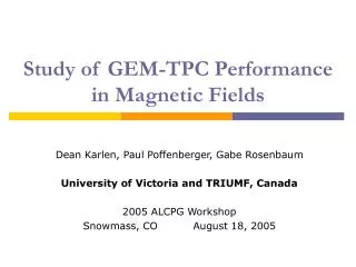
Transverse resolution - MT3-TPC with Triple GEMAr+5%CH4 E = 50 V/cm DTr = 102 µ/cm (Magboltz) @ 1T 2.3 x 6.3 mm2 pads s0= (72±2) mm Neff = 322 (stat.) LCWS Bangalore 2006
Summary & outlook • A first demonstration of the charge dispersion readout for the MPGD-TPC in a magnetic field in a KEK beam test. • Two TPCs tested using GEMs with 2.3 mm wide pads & Micromegas with 2 mm and 2.3 mm pads: about 500,000 events recorded for the Carleton TPC, & about 100,000 for the MPI-TPC. • Data analysis is in progress - promising first results. ~ 50 m resolution with Micromegas for short drift distances with 2 x 6 mm2 pads at 1 T. • Charge dispersion TPC readout works with GEMs & Micromegas both. • With proper choice of gas, the ILC-TPC resolution goal of ~100 m with 2 mm x 6 mm pads for all tracksappears within reach. • R&D plans - cosmic ray TPC tests at 4 T & two track resolution studies in beam. • R&D issues: New technology issues of fabrication & quality control, develop analysis techniques. As charge dispersion pulses are slow, ~25 MHz digitizers could be used. • Thanks to KEK and all the groups from Germany, France & Japan working together to make this test successful. LCWS Bangalore 2006
Additional slides LCWS Bangalore 2006
When there is no ExB effect, the wire/pad TPC resolution approaches the diffusion limit for the Aleph TPC TPC wire/pad readout ExB cancels track angle effect E not parallel to Bnear anodes 100 µm Average Aleph resolution ~ 150 µm. Resolution ~ 100 µm even for 2 m drift. Limit from diffusion (10 cm drift) ~ 15 µm; (2 m drift) ~ 60 µm. LCWS Bangalore 2006
Cosmic ray resolution of a MPGD-TPC 15 cm drift length with GEM or Micromegas readout B=0 Ar:CO2/90:10 chosen to simulate low transverse diffusion in a magnetic field. Aleph charge preamps. Rise= 40 ns, Fall = 2 s. 200 MHz FADCs rebinned to digitization effectively at 25 MHz. 60 tracking pads (2 x 6 mm2) + 2 trigger pads (24 x 6 mm2). The resolution was next measured with a charge dispersion resistive anode readout with a double-GEM & with a Micromegas endcap. The GEM-TPC resolution was first measured with conventional direct charge TPC readout. LCWS Bangalore 2006
Measured TPC transverse resolution for Ar:CO2 (90:10) R.K.Carnegie et.al., NIM A538 (2005) 372 R.K.Carnegie et.al., to be published Unpublished Compared to conventional readout, resistive readout gives better resolution for the GEM and the Micromegas readout. The z dependence follows the expectations from transverse diffusion & electron statistics. LCWS Bangalore 2006
Simulation - GEM TPC cosmic event with charge dispersion(track Z drift distance ~ 67 mm, Ar/CO2 90/10 gas) Detailed model simulation including longitudinal & transverse diffusion, gas gain, detector pulse formation, charge dispersion & preamp rise & fall time effects. 2x6 mm2 pads Simulation Data Centre pad amplitude used for normalization - no other free parameters. LCWS Bangalore 2006