Download

1 / 15
250 likes | 703 Vues
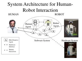
ROBOT ASSEMBLY. T. Bajd and M. Mihelj. Robot assembly. The knowledge on robot assembly is important when planning an intelligent control of a robot assembly cell, usually comprising robot vision, force control and special gripper.

E N D
ROBOT ASSEMBLY T. Bajd and M. Mihelj
Robot assembly The knowledge on robot assembly is important when planning an intelligent control of a robot assembly cell, usually comprising robot vision, force control and special gripper. The knowledge can be usfully applied when designing a product which is not to be only functional and aesthetic, but also convenient for simple and economic assembly.
2 DOF 3 DOF 1 DOF 0 DOF Robot assembly Mechanical assembly – stable composition of interconnected parts Part – rigid body which does not change its shape during the assembly process Stable mechanical assembly – connections between the parts are plane contacts Subassembly – stable subset of interconnected parts Functionality of subassembly – two parts can only be joined in a unique way
Graph of connections The parts belong to the nodes of the graph: P = {p1, p2, … pN} The connections correspond to the edges of the graph: C = {c1, c2, … cL} The connection c1has3 DOF, c2– 0 DOF, c3 – 2 DOF, c4 – 3 DOF and c5 – 0 DOF. The connection of the cup and bottom is not functional.
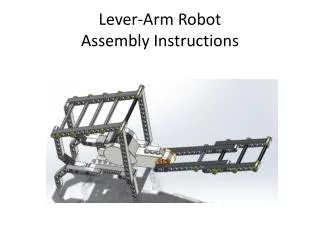
Assembly sequence • First screw the cup to the receptacle • Second insert the stick into receptacle • Finally screw the bottom to the subassembly of the receptacle, stick, and cup
Ordered list of assembly tasks ({{Cup}, {Receptacle}}, {{Cup, Receptacle}, {Stick}}, {{Cup, Receptacle, Stick}, {Bottom}}) } Number of elements N - 1
Ordered list of binary vectors ([F, F, F, F, F], [F, T, F, F, F], [T, T, T, F, F], [T, T, T, T, T]) [c1, c2, c3, c4, c5], } T – connection is established F – connection is not established Number of elements N
Ordered list of assembly states ({{Cup}, {Receptacle}, {Stick}, {Bottom}}, {{Cup, Receptacle}, {Stick}, {Bottom}}, {{Cup, Receptacle, Stick}, {Bottom}}, {{Cup, Receptacle, Stick, Bottom}}) } Number of elements N
Ordered list of connections ({c2}, {c1, c3}, {c4, c5}) } Number of elements N-1
Directed graph of assembly sequences The directed graph represents all the sequences for a mechanical assembly. The nodes are stable assembly states, while the edges belong to the connections. Each path between the initial and final state corresponds to a feasible assembly sequence.
Car automatic transmission system The mechanical assembly consists from 11 parts. The corresponding graph of connections has 18 possible connections or assembly tasks.
Car automatic transmission system The nodes of the graph are described by binary vectors. Different assembly costs can be assigned to the edges of the directed graph. The assemblies with a larger number of DOF are less stable and should be avoided, when searching for more advantageous assembly sequences.
AND/OR graph The AND/OR graph represents the set of all possible assembly sequences. The nodes represent the subassemblies. The arcs are feasible assembly tasks. The solutions of the AND/OR graph are feasible subassembly trees.
AND/OR graph The main advantage of the AND/OR graph is to show explicitely the possibility of simultaneous execution of assembly tasks. Subassembly tree corresponding to the sixth and seventh assembly sequence. Subassembly tree corresponding to first assembly sequence.
Strongly and weakly connectedmechanical assemblies Strongly connected assembly – every part is connected to every other part Weakly connected assembly – there are N – 1 connections between N parts Mechanical assembly of 10 parts Strongly connected assembly Directed graph: 115975 nodes AND/OR graph: 1023 nodes Directed graph: 512 nodes AND/OR graph: 55 nodes Weakly connected assembly