Download
1 / 10
100 likes | 296 Vues
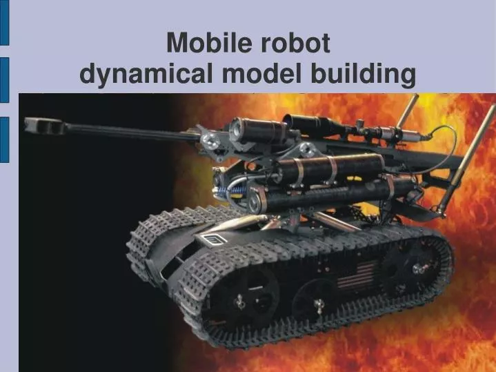
Mobile robot dynamical model building. Mobile robot dynamical model building. Main concepts Mobile robot model Simple representation Simulink model Engine model Definition and characteristics Diesel Engine block Gear model Simple Gear block Lepelletier 6-Speed transmission block

E N D
Mobile robot dynamical model building • Main concepts • Mobile robot model • Simple representation • Simulink model • Engine model • Definition and characteristics • Diesel Engine block • Gear model • Simple Gear block • Lepelletier 6-Speed transmission block • Propeller model • Tire block
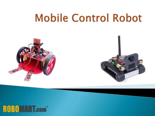
Main concepts • ́A robot is an electro-mechanical device that can perform autonomous or preprogrammed tasks. A robot may act under the direct control of a human or autonomously under the control of a programmed computer. Robots may be used to perform tasks that are too dangerous, difficult or tedious for humans to implement directly or may be used to automate mindless repetitive tasks that should be performed with more precision by a robot than by a mere human. • Mathematical simulation of robotic operations is the primary method of automatic control theory. Main purpose of this simulation is to predict system's operating characteristics on different reliefs within given travel ranges. • For precision simulation we need to define system's profile, travel conditions and relief.
Mobile robot model:simple representation For modelling of our system we need to describe different components first. This scheme represents our system in quite a simple way. Propeller Gear Engine torque, speed fuel, throttle torque, speed longitudinal force speed Mass Integrator Integrator acceleration X coordinate
Mobile robot model: Simulink model • This scheme represents robot in a more complex way. • This model includes not only main blocks, such as Engine block, Gear block and Tyre block, but also friction forces, inertia and gravity forces. • Model outputs coordinates in 2-dimensional Cartesian coordinate system (X-Y).
Engine model:Definition and characteristics • The Diesel Engine block models a diesel-fuel, compression-ignition engine. The engine runs at a variable speed that you can control with a Simulink throttle signal. The throttle signal directly controls the output torque that the engine generates and indirectly controls the speed at which the engine runs. The model does not include the air-fuel dynamics of combustion. • Characteristics: • Maximumpower • 900 kWatt • Speed at maximum power • 3500 rpm • Maximum speed • 4500 rpm • Throttle input • 0-1
Engine model:Diesel Engine block • The engine model uses a programmed relationship between torque and speed, modulated by the throttle signal. • The engine model is specified by an engine torque demand function g(Ω) built into the block. It provides the maximum torque available for a given engine speed Ω. • The throttle input signal T specifies the actual engine torque delivered as a fraction of the maximum torque possible in a steady state at a fixed engine speed. It modulates the actual torque delivered τ from the engine: τ = T·g(Ω). The actual engine drive shaft speed Ω is fed back to the engine input. • The demand function g(Ω) is specified in terms of the steady-state engine power P(Ω). • The engine speed is limited to a maximum: 0≤Ω≤Ωmax. The absolute maximum engine power Pmax defines Ω0 such that Pmax = P(Ω0). Define w = Ω/Ω0 and P(Ω) = Pmax·p(w). Then p(1) = 1 and dp(1)/dw = 0. Power is the product of torque and angular velocity. The torque demand function is thus: • g(w) = (Pmax/Ω0)·[p(w)/w]
Gear model:Simple Gear block • The Simple Gear block represents a gear box that constrains the two connected driveline axes to corotate with a specified fixed ratio. • The Simple Gear imposes a single constraint, specified by the fixed gear ratio gFB, on the motions and torques of the two axes: • ±gFB = ωB/ωF = τF/τB • The plus and minus signs refer to the axes corotating in the same or opposite directions. • If the Simple Gear represents two coupled gear wheels, the gear ratio is related to the ratio of the radii r of the gear wheels and the ratio of the number N of teeth on each gear wheel: • gFB = rF/rB = NF/NB • In our model the Simple Gear consists of 2 Gain blocks, one in straight loop and one in feedback loop.
Gear model:Lepelletier 6-Speed transmission • The Lepelletier 6-Speed transmission block is a subsystem that models a standard automotive transmission having six selectable forward gear ratios and a single reverse gear ratio. The Lepelletier gearbox is constructed by connecting a planetary gear to a Ravigneaux gear. The sun of the planetary gear is connected to the housing and cannot rotate. The carrier of the planetary gear is connected, by clutches (A and C), to the large and small sun wheels of the Ravigneaux gear, respectively. The input, or driver, shaft is always connected to the ring of the planetary gear and can simultaneously be connected to the carrier of the Ravigneaux gear using a separate clutch (B). The output, or driven, shaft is connected to the ring of the Ravigneaux gear. • This transmission subsystem has two independent internal degrees of freedom and therefore requires that two clutches be locked at any instant in order to achieve a unique drive ratio from the input shaft to the output shaft.
Propeller model:Tire block • The tire is a flexible body in contact with the road surface and subject to slip. When a torque is applied to the wheel axle, the tire deforms, pushes on the ground (while subject to contact friction), and transfers the resulting reaction as a force back on the wheel, pushing the wheel forward or backward. • The Tire block models the tire as a rigid wheel-flexible body combination in point contact with the road. The model includes only longitudinal motion and no camber, turning, or lateral motion. The flexible body is represented by a deformable, circumferential spring. • If the tire were rigid and did not slip, it would roll and translate as Vx = reΩ. But even a rigid tire slips, and the wheel slip velocity ≠ 0. • The tire is also flexible. Because it deforms, the contact point turns at a different angular velocity Ω′ from the wheel. • A tire model must provide the longitudinal force Fx the tire exerts on the wheel once the deformation, the contact slip, and the vertical load are given.