Download
1 / 68
720 likes | 1.04k Vues
Electrical actuation systems. Intro. Actuator is a device which is used to actuate a process. Actuate is to operate the process.

E N D
Intro.. • Actuator is a device which is used to actuate a process. • Actuate is to operate the process. • Switching devices – mechanical switches, eg. relay and solid state switches, eg diodes, thyristors and transistors app – switch on or off electrical devices • Solenoid – type devices used to actuate valves of hydraulic and pneumatic systems. (flow control) • Drive systems – DC motor, AC motor and stepper motor.
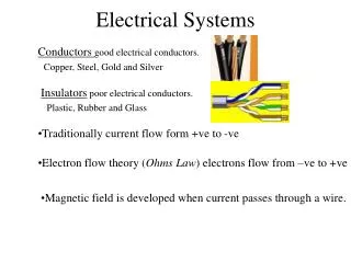
Basic electronics • Semi-conductor • Diode • Transistor • Resistor
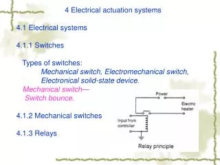
Mechanical switches • Relay - A relay is an electrically operated switch.
Relay • Electrically operated switches in which changing the current in one circuit switches a current on or off in another circuit. • NO – normally open , NC – normally closed • Output from controller is small so it is often used with transistor. • Relays are inductances • Free – wheeling or fly back diode. • Importance • To operate a device which needs larger current.
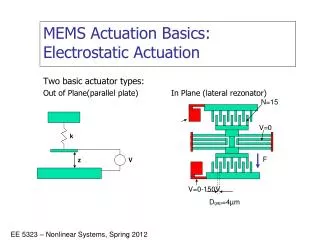
solenoid • Solenoid is an electromagnet which can be used as an actuator. • Electrically operated actuators. • Solenoid valves are used in hydraulic and pneumatic systems.
Solid state switches • diode • Transistor • Thyristor • Triac • Bipole transistor • MOSFET
Bipolar Transistors Transistors are manufactured in different shapes but they have three leads (legs). The BASE - which is the lead responsible for activating the transistor.The COLLECTOR - which is the positive lead.The EMITTER - which is the negative lead.
Transistor needs large base current to switch on. • Output from microprocessor has a small input. • A second transistor is employed to enable a high current to be switched on. Such a combination of pair of transistor is called Darlington pair.
MOSFET • Metal oxide field effect transistor • Two types • N channel • P channel • Three terminals • Gate (G) • Drain (D) • Source (S)
Operation • When MOSFET is turned on current flows from source to drain . • Voltage is applied between gate-source to turn on MOSFET. • MOSFET can be turned off by removing gate voltage. • Gate has full control over the control of MOSFET. • A level shifter buffer required to raise the voltage level at which the MOSFET starts to activate. • Interfacing with µp is simpler then transistor.
Thyristors have three states: • Reverse blocking mode — Voltage is applied in the direction that would be blocked by a diode • Forward blocking mode — Voltage is applied in the direction that would cause a diode to conduct, but the thyristor has not yet been triggered into conduction • Forward conducting mode — The thyristor has been triggered into conduction and will remain conducting until the forward current drops below a threshold value known as the "holding current"
Thyristor dimmers switch on at an adjustable time (phase angle) after the start of each alternating current half-cycle, thereby altering the voltage waveform applied to lamps and so changing its RMS effective value. • R1 is a current limiting resistor and R2 is a potentiometer. • By adjusting R2 thyristor can be made to trigger at any point between 0 deg and 90 deg.
Snubber circuit • In order to prevent sudden change in source voltage, the rate voltage changes with time is dV/dt is controlled by using a snubber circuit.
Drive systems • DC motor • AC motor • Stepper motor
Working principle • When current passes through the coil, the resulting forces acting on its sides at right angles to the field cause forces to act on those sides to give a rotation. • For the rotation to continue, when the coil passes through the vertical position the current direction through the coil has to be reversed.
Parts • Stator (permanent or non permanent magnet) • Rotor (electromagnet) • Armature • Commutator • Brush
A brush type dc motor is essentially a coil of wire which is free to rotate - termed as rotor in the field of permanent or non-permanent magnet. • The magnet termed a stator since it is stationery. • For the rotation to continue, when coil passes through vertical position the current direction is reversed which is got by use of brushes making contact with split ring commutator.
For an armature conductor of length l and carrying a current I, the force resulting from a magnetic flux of density B at right angles to the conductor is given by F = BIL • Torque produced along the axis of the conductor due to force F is T = F x b = nBIL x b = KI
Since armature is a rotating magnetic field it will have back emf Vb. The back emf depends on rate of flux induced in coil. Back emf is proportional to angular velocity w Vb = Kw • Equivalent circuit diagram for D.C motor
Neglecting the inductance produced due to armature coil, then effective voltage producing current I through resistance R is Va-Vb, hence • I = (Va - Vb)/R = (Va – Kw)/R T = K I = k(Va – Kw)/R
Control of brush type DC motor • Speed control can be obtained by controlling the voltage applied to the armature. Since fixed voltage supply is often used, a variable voltage is obtained by an electronic circuit. • When A.C supply is used a Thyristor can be used to control the average voltage applied to armature. • PWM – pulse width modulation • Control of d.c motors by means of control signal from microprocessors.
Brush type motor with non-permanent magnet • Series wound • Shunt wound • Compound wound • Separately excited
Series wound • Armature and field windings are connected in series. • Highest starting torque • Greatest no load speed • Reversing the polarity of supply will not effect the direction of rotation of rotor.
Shunt wound • Armature and field coils are in parallel. • Lowest starting torque • Good speed regulation. • Almost constant speed regardless of load. • For reversing direction of rotation either armature coil or field coil supply has to be reversed.
Compound wound • Two field windings one in series an another in parallel with armature windings. • High starting torque with good speed regulation.
Separately excited • Separate control of armature and field coils. • Speed of these motors can be controlled by separately varying the armature or field current.
Brush less dc motor • Its consists of a sequence of stator coils and a permanent magnet rotor. • Current carrying conductors are fixed and magnet moves. • Rotor is ferrite or permanent magnet. • The current to the stator coils are electronically switched by transistor in sequence round the coils. • Switching being controlled by position of rotors. • Hall effect sensors are used to input signals related to a particular position of rotor.
A.C motors • Single phase squirrel cage induction motor • Its consists of a squirrel cage rotor, this being copper or aluminum bars that fit into slots in end rings to form a complete circuit. • Its consists of a stator having set of windings. • Alternating current is passed through stator windings an alternating magnetic field is produced. • As a result EMF are induced in conductors in the magnetic field. • Initially when rotor is stationery net torque is zero. • Motor is not self starting.