Download
1 / 91
930 likes | 980 Vues
Dive into the IEEE 802.3 Ethernet LAN protocols, from its origins in the 1970s to the development of Carrier Sense Multiple Access. Learn about ALOHA and why CSMA improved efficiency in LAN networks.

E N D
Local Area Networks Chapter 7 Ethernet LANs 635.412 Class #3
IEEE 802.3 Family of LAN ProtocolsEthernet • Introduction & History • The most widely used LAN technology today is Ethernet and its successive generations – and it is to this day still evolving! • Ethernet was originally developed in early 1973 at the Xerox Palo Alto Research Center (PARC); it originally ran at 2.94-Mbps • In 19xx Bob Metcalfe and Charlie Roll were granted Patent #4,063,220 • Metcalfe persuaded Xerox to partner with other companies, resulting in the initial effort to standardize Ethernet • The first widespread standard for 10-Mbps Ethernet was ratified by DEC, Intel, and Xerox in 1980 with a major revision in 1983 • The IEEE 802.3 working group developed a vendor-neutral standard based on these earlier standards (though there are slight differences they are compatible) Class #3: Ethernet LANs
IEEE 802.3 Family of LAN ProtocolsEthernet • What are the essential components of Ethernet? • There are three components of Ethernet to study • MAC Algorithm • Based on a mechanism called Carrier Sense Multiple Access with Collision Detect (CSMA/CD) • MAC Frame • Physical Layer Standards Class #3: Ethernet LANs
IEEE 802.3 Family of LAN ProtocolsPrecursors to CSMA/CD and Ethernet • CSMA/CD is a contention based mechanism that has evolved from several different earlier random access schemes • The earliest contention mechanism used was called ALOHA • ALOHA was developed in the late 1960s for use in packet radio networks at the University of Hawai’i • How ALOHA works: • A station may transmit a frame at any time • After a station transmits it listens to the medium for an amount of time equal to the maximum round-trip propagation time plus a small fixed increment • If a station receives an acknowledgement during that time the frame was properly received, otherwise the transmitter resends the frame • A received frame is checked for errors which may be due to noise or a collision (in either case the errored frame is ignored) • While stations using ALOHA are very simple, it is very inefficient with a maximum utilization around 18% Class #3: Ethernet LANs
Pure Aloha efficiency P(success by given node) = P(node transmits) . P(no other node transmits in [p0-1,p0] . P(no other node transmits in [p0-1,p0] = p . (1-p)N-1 . (1-p)N-1 = p . (1-p)2(N-1) … choosing optimum p and then letting n -> infty ... = 1/(2e) = .18 Even worse ! Class #3: Ethernet LANs
IEEE 802.3 Family of LAN ProtocolsPrecursors to CSMA/CD and Ethernet • Later, an improvement known as slotted ALOHA was developed • The medium is divided into uniform time slots (this requires some kind of synchronization mechanism available to all stations) • Transmission is permitted to begin only on slot boundaries; otherwise this works the same as regular ALOHA • This forces collisions to overlap entirely, protecting transmissions somewhat from failure • This increases efficiency to a maximum around 37% at the expense of a more complex system • The core problem with both Aloha and slotted ALOHA was that they didn’t take advantage of the short propagation delay in the LAN/packet radio environment; better feedback about network conditions can be used to increase efficiency Class #3: Ethernet LANs
Cons collisions, wasting slots idle slots nodes may be able to detect collision in less than time to transmit packet Slotted ALOHA Pros • single active node can continuously transmit at full rate of channel • highly decentralized: only slots in nodes need to be in sync • simple Class #3: Ethernet LANs
For max efficiency with N nodes, find p* that maximizes Np(1-p)N-1 For many nodes, take limit of Np*(1-p*)N-1 as N goes to infinity, gives 1/e = .37 Efficiency is the long-run fraction of successful slots when there’s many nodes, each with many frames to send At best: channel used for useful transmissions 37% of time! Slotted Aloha efficiency • Suppose N nodes with many frames to send, each transmits in slot with probability p • prob that 1st node has success in a slot = p(1-p)N-1 • prob that any node has a success = Np(1-p)N-1 Class #3: Ethernet LANs
IEEE 802.3 Family of LAN ProtocolsPrecursors to CSMA/CD and Ethernet • Carrier Sense Multiple Access (CSMA) • Experience with ALOHA and slotted ALOHA led to the development of a new technique called Carrier Sense Multiple Access (CSMA) • With CSMA a station wishing to transmit first listens to the medium to see if it in use; if so it waits until the medium is idle • If a collision occurs or no acknowledgement is received the station must retransmit the frame • CSMA works best in a medium where the propagation delay is small and stations quickly determine that someone else is transmitting • The maximum utilization with CSMA is far better than ALOHA or slotted ALOHA, but varies with the frame size and propagation time Class #3: Ethernet LANs
CSMA collisions spatial layout of nodes collisions can still occur: propagation delay means two nodes may not hear each other’s transmission collision: entire packet transmission time wasted note: role of distance & propagation delay in determining collision probability Class #3: Ethernet LANs
IEEE 802.3 Family of LAN ProtocolsCarrier Sense Multiple Access (CSMA) • Persistance • If a station wishing to transmit finds the medium idle, there are several different methods for how the station should react • With nonpersistant CSMA, if the medium is idle the station waits a random amount of time before transmitting • Random delay helps reduce the possibility of collisions • Utilization of the medium is affected by the delay because the medium will generally remain idle even though one or more stations have frames to transmit • In effect, the station acts very conservatively when competing for the medium Class #3: Ethernet LANs
IEEE 802.3 Family of LAN ProtocolsCarrier Sense Multiple Access (CSMA) • Persistance • To increase efficiency 1-persistent CSMA can be used • In this case once the medium is found to be idle a station transmits immediately • Very efficient at low loads however, if two or more stations are waiting to transmit they will collide (which could induce gridlock) • In effect this makes stations very greedy, automatically trying to capture the medium Class #3: Ethernet LANs
IEEE 802.3 Family of LAN ProtocolsCarrier Sense Multiple Access (CSMA) • Persistance • A compromise to these two extremes is to use p-persistent CSMA • In this case if the medium is found idle the station transmits immediately with probability p or otherwise delays transmission for one time unit • If the station delays it will again have to sense that the medium is idle before transmitting • The choice of p is very important; too high can cause too many collisions if a lot of stations wish to transmit while having p too low will result in long delays for stations with frames to send • An adaptive value for p is an active area of LAN research Class #3: Ethernet LANs
IEEE 802.3 Family of LAN ProtocolsCSMA with Collision Detection (CSMA/CD) • More enhancements to CSMA • While CSMA is a big improvement over ALOHA, it still has one key efficiency problem: dealing with collisions • This can be quite a blow to efficiency if a station continues to transmit the whole frame even though it has collided with another transmission (especially for long frames) • The fix is to ensure that the transmitting station continues to listen while transmitting and if a collision is detected stop transmitting as soon as possible • The specific CSMA/CD procedure: • If medium is idle then transmit, if not go to (b) • If medium is busy, listen for medium to become idle & transmit • If a collision is detected during transmission transmit a brief jamming signal and stop • Wait a random amount of time and return to (a) Class #3: Ethernet LANs
CSMA/CD collision detection Class #3: Ethernet LANs
IEEE 802.3 Family of LAN ProtocolsCSMA with Collision Detection (CSMA/CD) • Description of CSMA/CD • Example of CSMA/CD operation [Figure 7.2] • Signal Propagation • Signal Overlap • Collision Detection by the first station • Collision Detection by the second station • With CSMA/CD the wasted utilization on the medium is reduced to the amount of time it takes to detect a collision (twice the maximum propagation time of the network) • In order to ensure collision detection all frames must be long enough to allow collision detection before the end of transmission (or it wouldn’t be collision detection!) Class #3: Ethernet LANs
IEEE 802.3 Family of LAN ProtocolsCSMA/CD Operation Class #3: Ethernet LANs
IEEE 802.3 Family of LAN ProtocolsCSMA/CD and Persistent Retransmission • Though the basic 1-persisent protocol can have performance problems, an enhanced version is used with Ethernet • This is possible because the time wasted with collisions is usually short & all stations use a random backoff after a collision (so someone retransmits quickly) • The specific method used in Ethernet is called binary exponential backoff • Stations try to transmit repeatedly after collisions, but each time the mean delay is doubled (delay(k)=random[0,(2^k -1)x slot time]) • After 16 unsuccessful tries, the station gives up and reports an error • With a 1-persistent protocol and binary exponential backoff Ethernet is efficient over a wide range of loads • Minimizes transmission delay at low loads while sorting out collisions quickly at higher loads • Unfortunately this combination of techniques has a LIFO effect with stations wishing to transmit Class #3: Ethernet LANs
IEEE 802.3 Family of LAN ProtocolsCarrier Sense and Collision Detection • So what really is a Collision? • With baseband Ethernet systems the ‘carrier’ is sensed by detecting the presence of voltage transitions on the medium • A collision is detected if a station detects a signal exceeding the maximum that could be transmitted by the station alone • Because of attenuation this may not work if stations far apart suffer a collision • This limits the maximum span of the network; in the IEEE 802.3 standard the limit is 500m • Since repeaters are supposed to allow transparent expansion of the network, they must pass collisions • In star-wired twisted pair networks collisions are handled in a much simpler way, since collision detection is done with logic circuits instead of voltage sensing Class #3: Ethernet LANs
IEEE 802.3 Family of LAN ProtocolsCarrier Sense and Collision Detection • Operation in Star-wired twisted pair networks • For any hub, if frames are received simultaneously on two or more inputs a collision has occurred • A special collision presence signal is generated at all hub ports and is propagated throughout a hierarchal star topology [Figure 7.3] Class #3: Ethernet LANs
IEEE 802.3 Family of LAN ProtocolsSummary of CSMA/CD Operation • If the medium is idle for at least the IFG (inter-frame gap) time interval (96 bit times), then transmit the frame immediately • If the medium is busy, then wait until the medium is idle and start with step #1 • If a collision is detected during transmission, continue to send data until the complete preamble and 32 bits of data are sent (the ‘jamming’ signal) • The jam signal should be long enough to ensure all other stations are alerted to a collision • The stations involved in the collision wait a random (backoff) time and start at step #1 • These station keep a collision counter to track the number of collisions that have occurred in the process of transmitting a specific frame Class #3: Ethernet LANs
IEEE 802.3 Family of LAN ProtocolsSummary of CSMA/CD Operation • If a collision occurs and the collision counter is greater than zero, the random backoff time is doubled • Once a station has transmitted the preamble and 512 bits of a frame (called the slot time), the station has acquired the medium • After this point all other stations should be aware of the transmission, so no other station should attempt to transmit • Late collisions are serious errors; a typical cause is a duplex mismatch on a link • Once a frame is successfully transmitted the collision counter is cleared so the backoff process starts anew Class #3: Ethernet LANs
IEEE 802.3 Family of LAN ProtocolsEthernet at the MAC Layer • MAC frame format for the IEEE 802.3 protocol Class #3: Ethernet LANs
IEEE 802.3 Family of LAN ProtocolsEthernet at the MAC layer • MAC frame format for the IEEE 802.3 protocol • Preamble: 56 bits of alternating ones & zeros to allow bit synch • Start Frame Delimiter: the bit sequence 10101011 • Destination Address (DA): 48 bit unicast, broadcast, or multicast address • Pad: necessary to ensure short frames allow collision detection to occur • Source Address (SA): 48 bit unicast address • Length/Type: Field contains either the actual length of the frame (up to a maximum of 1518 bytes) if a IEEE 802.3 standard frame or the payload type if frame conforms to earlier Ethernet standard • LLC Data: the LLC PDU • Frame Check sequence (FCS): a 32 bit cyclic redundancy check Class #3: Ethernet LANs
Exercises • Question 1: Find the Medium length when Slot time (ST) and data rate (R) are (standards for 802.3): • ST=512 bits and R=10 Mbps, • ST=512 bits and R=100 Mbps, • ST=4096 bits and R=100 Mbps, • Question 2: The header of IP, TCP, LLC, and MAC are 20 bytes, 20 bytes, 2 bytes, and 26 bytes, respectively. Assume a frame F contains a payload of 64 bytes (64-1518 bytes for 802.3). What should be the MAC frame padding size to transmit F on a LAN where Tp=51.2 micro seconds and R=100 Mbps. Class #3: Ethernet LANs
IEEE 802.3 Family of LAN Protocols10-MbpsEthernet • Introduction to the Physical Layer • The IEEE 802.3 committee has been very good at responding to the evolution of technology by introducing new physical layer media, but that has led to enough options to make the choice daunting for customers • Physical Layer Medium Alternatives [Table 7.2] • 1BASE-T • 10BASE-5 • 10BASE-2 • 10BASE-T • 10BROAD-36 • 10BASE-F Class #3: Ethernet LANs
IEEE 802.3 Family of LAN Protocols10-MbpsEthernet • Medium Attachment Unit • The IEEE 802.3 standard provides a solution for the situation where the networked station is some distance from the actual attachment to the Ethernet transmission medium • This requires the transmission functionality to be split into two components • The piece of equipment actually connected to the medium is called the Medium Attachment Unit (MAU) and performs the following functions: • Transmit to & receive signals from the medium • Recognize the presence of signals on the medium • Recognize a collision Class #3: Ethernet LANs
IEEE 802.3 Family of LAN Protocols10-MbpsEthernet • Medium Attachment Unit • The MAU is connected to the rest of the network interface hardware at the station by a set of cables called the Attachment Unit Interface (AUI) that meet the relevant IEEE 802.3 specifications • AUI details • Detailed electrical interface specifications • Uses D-type 9 or (more common) 15 pin connector • 8 shielded wires typically used: one pair for Transmit and one pair for Receive Data • One pair for Collision signaling • Power is also supplied through interface to MAU • Maximum distance of 50m Class #3: Ethernet LANs
IEEE 802.3 Family of LAN Protocols10-MbpsEthernet • Medium Attachment Unit Class #3: Ethernet LANs
IEEE 802.3 Family of LAN Protocols10-MbpsEthernet • 10BASE-5 Medium Specification • The original 802.3 physical medium specification based directly on the earlier DIX Ethernet specification • Special purpose 50 ohm coax cable & baseband Manchester signaling is used • The maximum length of any coaxial segment is 500m, a maximum of four repeaters between any two stations allows a maximum network size of 2.5 km • There can only be one path between any two stations; loops are not allowed Class #3: Ethernet LANs
IEEE 802.3 Family of LAN Protocols10-MbpsEthernet • 10BASE-2 Medium Specification • This physical layer specification was developed to provide a cheaper, easier to install alternative to 10BASE-5 for personal computer networking • Thinner 50 ohm coaxial cable is used and all electronics are housed on the Network Interface card (NIC) • Higher attenuation and noise figures for the thinner cable limits the maximum cable size and number of stations • It is possible to interconnect 10BASE-5 and 10BASE-2 segments using appropriate repeaters, but a 10BASE-2 segment should not be used to interconnect two 10BASE-5 segments Class #3: Ethernet LANs
IEEE 802.3 Family of LAN Protocols10-MbpsEthernet • 10BASE-F Medium Specification • Even though fiber was very expensive and unusual to use at the time, the IEEE considered it important to provide a fiber optic transport option • All variants use a pair of multi-mode fiber: one TX & one RX fiber (ST connectors) • Physical signaling is intensity modulation with Manchester encoding • The original option was called FOIRL (Fiber Optic Inter-Repeater Link) • Later, FOIRL was replaced by a more comprehensive specification with three options for fiber-based Ethernet • 10BASE-FL • 10BASE-FB • 10BASE-FP Class #3: Ethernet LANs
IEEE 802.3 Family of LAN Protocols10-MbpsEthernet • FOIRL and 10BASE-FL • The FOIRL standard was first published officially in 1989 • Designed to allow easy extension of an Ethernet segment between two buildings (point-to-point) • Maximum distance of 1000 meters • Only for repeater <-> repeater links • Some vendors developed FOIRL capable stations but this functionality never standardized • Replaced in 1993 with an enhanced standard called 10BASE-FL • Backwards compatible with FOIRL repeaters • Maximum distance of 2000 meters • Can connect together two repeaters, two stations, or a station and a repeater Class #3: Ethernet LANs
IEEE 802.3 Family of LAN Protocols10-MbpsEthernet • 10BASE-FB and 10BASE-FP • Two other variants standardized at the same time as 10BASE-FL for other uses • 10BASE-FB defines synchronous signaling fiber backbone segment • Allows multiple repeaters to be linked over the normal repeater limits • Used to build lengthy backbone segments • Not currently used in commercially available products • 10BASE-FP defines a fiber-based Ethernet segment that can have up to 33 stations • Uses a passive fiber equipment & couplers to build a network up to 500 meters in diameter • Never developed into commercially available equipment Class #3: Ethernet LANs
IEEE 802.3 Family of LAN Protocols10-MbpsEthernet • 10BASE-T Medium Specification • By using a star topology and sacrificing some distance on the length of cable runs twisted pair can be used as a 802.3 physical layer medium • All stations are connected in a physical star topology back to a central hub/repeater with two twisted pairs (one send/one receive) • The length of each link is limited to 100m; like the other physical layers specifications there is a maximum span of five ‘segments’ and four repeaters • It is possible to mix 10BASE-T with 10BASE-5 and 10BASE-2 segments (the maximum number of coax segments in a ‘mixed’ network is three) Class #3: Ethernet LANs
IEEE 802.3 Family of LAN Protocols10-MbpsEthernet • 10BASE-T Physical Layer • Requires two pair of Category 3 UTP (or better) • Uses Manchester signaling across a differential interface • The familiar RJ-45 interface is used with the following pin configuration: • Pin 1: TD+ • Pin 2: TD- • Pin 3: RD+ • Pin 4: Unused • Pin 5: Unused • Pin 6: RD- • Pin 7: Unused • Pin 8: Unused Class #3: Ethernet LANs
IEEE 802.3 Family of LAN Protocols10-MbpsEthernet • 10BASE-T Hubs • Hubs have the following functionality and do not care whether a port is connected to a station or another hub: • A valid signal on any port is repeated on all other links • If a collision occurs a collision presence signal is generated on all ports • If a collision presence signal is detected on a port, it is repeated on all other links • More sophisticated hubs will have some network management capability • Collection of statistics • Disconnecting ‘misbehaving’ ports Class #3: Ethernet LANs
IEEE 802.3 Family of LAN Protocols10-MbpsEthernet • Simple 10BASE-T configuration with Hubs [Fig. 7.5] Class #3: Ethernet LANs
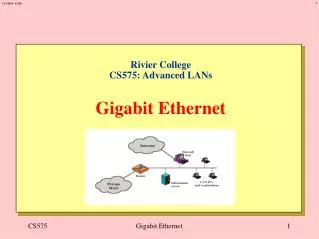
IEEE 802.3 Family of LAN Protocols100-MbpsEthernet • Introduction • Also known as Fast Ethernet, this technology was first developed by Kalpana in 1991-1992 • Shortly afterward, a standard specification was developed by the IEEE 802.3u subcommittee to fill the need for a low-cost, Ethernet-compatible 100-Mbps LAN technology • All of the 100BASE-T physical layer options use the standard IEEE 802.3 MAC protocol and frame format • Like 10-Mbps Ethernet a number of physical layer options were developed to allow network designers more flexibility • Options were developed for fiber optic and twisted pair cabling • In addition, a standard interface between the MAC and physical (PHY) layers was developed to facilitate this Class #3: Ethernet LANs
IEEE 802.3 Family of LAN Protocols100-MbpsEthernet 100BASE-T Options • 100BASE-X (2 links: Transmit & Receive): • 100BASE-TX uses TP and UTP (2 CAT 5 UTP or 2 STP) and MLT-3. • 100BASE-FX uses 2 FO (T & R) using 4B/5B NRZI • 100BASE-T4 uses 4 CAT 3 or CAT 5 UTP and 8B6T Class #3: Ethernet LANs
IEEE 802.3 Family of LAN Protocols100-MbpsEthernet Physical Layer • 100BASE-X Physical Layer Specifications • The two transmission options under the 100BASE-X specification provide a full duplex 100-Mbps link operating over a pair of physical links (one send/one receive) • The 100BASE-TX option uses two pairs of twisted pair cabling for the connection • Either Category 5 or Shielded twisted pair can be used with a maximum segment length of 100m • A signaling scheme called MLT-3 is used • A later standard called 100BASE-T2 allowed fast Ethernet to run over two pairs of Category 3 cable; however it has never been implemented Class #3: Ethernet LANs
MLT-3 Signaling Class #3: Ethernet LANs
Digital Signal Encoding for 100BASE-T • MLT-3 Encoding • While 4B/5B is great for fiber optic links, it’s spectral characteristics are unsuitable for UTP (radiates a large amount of RF interference) • Used with 100BASE-TX and the twisted pair version of FDDI • A ternary voltage encoding scheme that produces a transition for every binary one • The 4B/5B and NRZ-I encoding schemes are still used, but after that the elements are reconverted to NRZ, scrambled, and then encoded using MLT-3 for transmission • Example MLT-3 encoding [Figure 7.16]: Class #3: Ethernet LANs
IEEE 802.3 Family of LAN Protocols 100-MbpsEthernet • 100BASE-X Physical Layer Specifications • The 100BASE-FX option uses one pair of fiber optic cabling and a 4B/5B-NRZI encoding scheme • On fiber a binary signaling mechanism (intensity modulation) is used • Essentially the ANSI X3T9.5 FDDI physical layer standards have been reused • The standards address operation over Multimode Fiber cable (up to 2km); there are ‘proprietary’ 100BASE-FX products that operate over Single Mode Fiber (up to 10km) Class #3: Ethernet LANs
IEEE 802.3 Family of LAN Protocols 100-MbpsEthernet Physical Layer Options • 100BASE-T4 • Another transmission option which allows the use of lower grade Category 3 cabling for data transmission • Four pairs are needed for 100BASE-T4; each direction of the 100Mbps data link is split equally over three pairs • Pairs 1, 3, and 4 are used for data transmission while pairs 2, 3, & 4 are used for data reception • Pairs 3 and 4 must be configured for bi-directional communication • Pair 2 is also used for collision detection • Note that true full-duplex [symmetrical speeds] operation is not possible! • To provide high data rates over Category 3 UTP a ternary signaling scheme called 8B6T is used Class #3: Ethernet LANs
IEEE 802.3 Family of LAN ProtocolsDigital Signal Encoding for 100BASE-T • 8B6T Encoding • Another ternary encoding scheme used with 100BASE-T4 where a block of 8 data bits is encoded into a block of 6 ternary symbols • +V, 0, and –V are the three voltage levels used • The resulting stream is transmitted round-robin across the three transmit pairs leading to a signaling rate of 25-Mbaud on each pair • The mapping table [Table 7.6] outlines the 8B/6T code translation; the mappings were chosen to maintain proper timing and dc balance (under certain circumstances 6T code groups can be inverted for transmission to help maintain DC balance) • Theoretically similar the 4B/5B and other block encoding schemes except ternary symbols are used Class #3: Ethernet LANs
100BASE-T4Category 3 UTP and 8B6T signaling • How to get 100 Mbps using 3 UTPs (fourth UTP for collision) • 8 binary (256 levels) encoded as 6 Ternary, • 6 Ternary (729 levels): to each combination of 8-bit we have one combination (transmittable) of 6 ternary signals, • Each UTP is assigned 2 ternary (3 UTP get 6 ternary), • Since each UTP (25 Mbaud) gets 2 T, then the data rate is (25/2) x 8 bits = 100 Mbps. Class #3: Ethernet LANs
IEEE 802.3 Family of LAN Protocols 100-MbpsEthernet • Another variant: 100VG-AnyLAN • An alternative to the CSMA-CD protocols that was developed by the IEEE 802.12 task force • Uses a MAC technique called demand priority (round robin with priority enhancements) • Uses all four pairs with 5B6B encoding in half-duplex operation • Supports the 802.3 MAC frame format for interoperability with regular Ethernet • Originally a competitor to 100BASE-T – never been widely adopted Class #3: Ethernet LANs
IEEE 802.3 Family of LAN Protocols 100-MbpsEthernet • 100BASE-X Media Independent Interface (MII) • This was developed with the standard to allow different but interoperable physical layers to be developed for a single MAC layer • Defines an electrical and mechanical interface for Fast Ethernet similar in function to the 10-Mbps AUI • Uses 40-pin miniature D-type connector • Uses digital-logic grade signals capable of a 0.5m maximum distance • Separate clock, data, and power pins; 4 bits transferred in parallel on both transmit and receive • The MII was rarely used; most 100BASE-X equipment has the transceiver built on the NIC Class #3: Ethernet LANs