Download
1 / 30
730 likes | 1.88k Vues
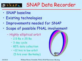
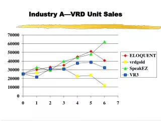
Voyage Data Recorder (VDR). Model VR-5000. 1. Purpose of VDR.

E N D
Voyage Data Recorder (VDR) Model VR-5000
1. Purpose of VDR The purpose of the Voyage Data Recorder (VDR) is to maintain a store, in a secure and retrievable form, of information concerning the position, movement, physical status, command and control of a vessel over the period leading up to, and following, an incident having an impact thereon. This information is for use during any subsequent investigation to identify the cause(s) of the incident. Incident Investigation Picking up Capsule
Standard: IMO A.861(20),IEC61996 Recording Time: More than 12 hours Final Recording Medium: Shall be installed in a protected Capsule Interface: IEC61162, or other means Power Source: Capable of operating from the ship’s emergency power source Reserve Power Source: The VDR shall continue to record bridge audio from a dedicated reserve power source for a period of 2 hours Playback Equipment: Data recorded shall be retrieved for test and investigation Protected CapsuleThe capsule shall enclose the final recording medium. The final recording medium shall not be accessible by standard operating procedures during normal ship operations.A means shall be provided to retrieve stored information via an external device without opening the protective capsule. 3. Performance Standard
Required specifications for Protected Capsule Location Beacon: Acoustic underwater beacon operating 25-50 kHz is included Environment condition: a) Shock: A half sine wave pulse of 50 G, with a duration of 11 ms b)Penetration: A mass of 250 kg with a pin of 100 mm diameter, dropped from a height of 3 m c)Fire: A low temperature fire of 260°C nominal for 10 hours. A high temperature fire of 1,100°C nominal for 1 h d)Deep-sea pressure and immersion: Immersion in sea water at a pressure of 60 MPa (equivalent to a depth of 6,000 m)
The protective capsule shall be sited in the vicinity of the bridge on the external deck area of the vessel. The capsule shall be positioned clear of rigging and other potential obstructions and as near to the center line of the ship as practically possible. Criteria to be considered when assessing the optimum position shall include but not be limited to the following: 1) separation from fuel or other potential fire sources. 2) separation from probable sources of mechanical damage. 3) operational environment for continued serviceability. 4) accessibility for copying of recorded data and for routine maintenance. 5) facilitation of underwater removal and retrieval by both divers and ROVs. There shall be a clear unobstructed space in the vicinity of the capsule to allow an ROV or diver to work. 6) in the case of float-free configuration, minimization of the risk of obstruction after release Installation of Capsule
4. Interface Interfacing to the various sensors required shall be in accordance with the relevant international interface standard, IEC 61162 series, where possible. Any interface units which may be required to convert non-IEC 61162 signals, shall conform to the requirements of IEC 60945.
5. Data To Be Recorded The status of all IMO mandatory alarms shall be recorded by the bridge audio and as a data parameterwhere practicable.
6. Annual Performance Test (Required by revised SOLAS Chapter V, Regulation 18) The Voyage Data Recorder system, including all sensors, shall be subjected to an annual performance test. The test shall be conducted by an approved testing or servicing facility to verify the accuracy, duration and recoverability of the recorded data. In addition, tests and inspections shall be conducted to determine the serviceability of all protective enclosures and devices fitted to aid location. A copy of the certificate of compliance issued by the testing facility, stating the date of compliance and the applicable performance standards, shall be retained on board the ship.
FURUNO’s VR-5000 System Overview
1. Standard Components • 1 x Data Collecting Unit with status display(included in 19” rack) • 1 x Data Recording Unit(with 30 m IEEE1394 cable) • 1 x Junction Box (included in 19” rack) • 1 x VHF Interface Unit • 6 x Microphones
2. Optional Supply • Additional Junction Box with PC board (Same specifications of standard Junction Box) • Remote Junction Box (For connection with sensors located remote location through Ethernet) • Additional VHF Interface Unit • Flush memory for Data Recording Unit (Required when connected with more than 2 radars) • Playback Software
3. Interface Specifications of VR-5000 *1 Optional memory is required for more than 2 radar inputs. *2 2ch for VHF, 6ch for bridge audio Remote Junction Box (option) • Power supply: 24 VDC • 1 x RJ45 port to be connected with Data Collecting Unit through Ethernet
4. Recording Radar Images How many radars? • One radar is sufficient. (No.1 ARPA Radar) • One input with up to SXGAIf more than two radars are connected, optional memory for Data Recording Unit is required. • Signal shall meet the VESA DMTS(RGB HV in VGA, XGA, SXGA) • One complete radar screen video frame shall be acquired at intervals of 15 s or less Radar Video Required FURUNO VR-5000
Radar Video accepted by VR-5000 • Specifications of Radar Input • Input levels:1V. peak to peak nominal, 2.0V p-p max. 50mV minimum sync level, when using composite sync. • Input impedance:75 Ohms. coaxial connection. • Conversion rate:0 to 80 MHz. • Horizontal sync-rate:Max. 72 Hz. • Vertical sync-rate:Max. 65 KHz. • Both InterlacedandNon-Interlaced Video acceptable *Optional buffer board required for FURUNO radars. Ask radar manufacturer for further details.
5. Recording VHF communications • 2 channels available(1 x VHF Interface Unit which enables to record TX/RX voice for one VHF is supplied as standard. If one more VHF is connected, additional VHF Interface unit is required.) How many VHF’s? • One VHF is sufficient. FURUNO VR-5000
How to connect VHF? Connector Handset With FURUNO FM-8500/8700 FM-8500/8700 VHF Interface Unit VDR TX Voice TX/RX Voice RX Voice 24 VDC With other VHF Cut cable! (Ask VHF manufacturer for further details) Handset VHF Interface Unit VHF RT VDR TX Voice TX/RX Voice RX Voice 24 VDC
Note 6. Recording Bridge Audio How many Microphones required? • One or more microphone shall be placed. As far as is practicable, the positioning of microphones shall also capture the input and output of intercom, public address systems and the audible alarms on the bridge. Where? • Near bridge Work Station defined as • Center line conning • Bridge wing(s) • Main radar • Chart table • Helmsman • Communication FURUNO VR-5000 • Six (6) microphones with amplifier are supplied as standard.
Recommended installation of microphones MIC 1 MIC 3 MIC 2 MIC 4 MIC 5 MIC 6
7. Recording Analog/Contact Closure Data • Basically, data format in IEC61162 is recommended. However, most of data for alarm systems, door status, engine orders, etc can be obtained in a form of Analog or Contact Closure. How to record Analog or Contact Closure data? FURUNO VR-5000 VR-5000 also records Analog and Contact Closure signals as well as IEC61162 data. (see page 13) • Remote Junction Box (option) • Contact Closure: 24ch • Analog: 12ch(0 to 10VDC or 4 to 20 mA ) • Standard • Contact Closure: 96ch • Analog : 16ch(0 to 10VDC or 4 to 20 mA ) • The same Junction Box is supplied as option for additional inputs.
8. Specifications of VR-5000 Principal features of Data Collecting Unit (DCU) • Constructed with use of standard industrial rugged PC. • All relevant data present on the bridge is connected to the DCU trough cables. • Enables to turn on and off the entire system for maintenance or other reasons. By turning the unit on, the data collection automatically starts. • The power switch is key operated and the on/off sequence generates a log file with date and time. • The normal operation does not require any operation or attention from the crew. • Maintains data integrity check continuously and displays an alarm message and sounds an audible alarm if one ore more faults occur.
Specifications of Data Collecting Unit (DCU) • Constructed with use of standard industrial rugged PC meeting IEC60945 environment test standard (EMC) • Power Supply • 1. Main power input:96 to 250 V AC 50/60 Hz, approx. 300 Watt. • 2. Secondary power input:9 to 32 V DC, approx. 300 Watt. • 3. Internal battery backup power: 24 volt. 24 Ah. sealed Lead-acid battery. (Internal battery is placed in Junction Box.
Specifications of Data Recording Unit (DRU) • Allows 13-hour recording with 3.3G Bytes memory • IEEE1394 (30 m cable standard) is used between DCU and DRU for higher data communication • The capsule shall maximize the probability of survival and recovery of the final recorded data after any incident. • The storage device can be overwritten and erased in excess of 100,000 times thus providing the VDR with a theoretical life span of more than 137 years in a 12 hour refresh cycle mode.
Environment Test for Data Recording Unit Shock:A half sine wave pulse of 50 g, with a duration of 11 ms, as specified in table II of IEC 60068-2-27. Penetration:A mass of 250 kg with a pin of 100 mm diameter, dropped from a height of 3 m, as specified in 5.3.2b of ED 56A.
Fire:A low temperature fire of 260°C nominal for 10 hours, as specified in 5.3.2e of ED 56A. A high temperature fire of 1,100°C nominal for 1 h, as specified in 5.3.2e of ED 56A. Deep-sea pressure and immersion:Immersion in sea water at a pressure of 60 MPa (equivalent to a depth of 6 000 m), as speci-fied in 5.3.2f of ED 56A.
Connector 9. Dimension for DRU Weight: 20 kg Acoustic Pinger
10. Dimension for DCU Weight: 20 kg
VDR-5000ユニット配置例 11. Example of VR-5000 installation Gyro/Autopilot RADAR, VHF, etc Alarm Panel, Thruster, etc. GPS, Speed Log Fire Alarm, etc ETHERNET Engine Monitoring, etc IEEE 1394 VR-5000 Capsule
12. Connection Diagram (For FURUNO Radars, optional buffer board required) Data Recording Unit Radar 1ch IEEE1394 (30 m) PC w/optional Playback software Standard IEC61162 (RS422) GPS Gyro Log Echo sounder Wind Main alarms Ethernet Remote Junction Box • 4 x IEC61162 • 24 x Contact • 12 x Analog 8ch Ethernet Data Collecting Unit Standard Contact Closure Doors / hatches Watertight doors Pumps / valves 1ch VHF IF 96ch 1ch VHF IF Standard Analog Signals Rudder Wheel Machine Bow thrusters Optional 6 x Microphonesw/Amp 16ch 96-250 VAC 50/60 Hz 19-32 VDC
FURUNO’s Worldwide Service Network FURUNO Service Agents in our Deepsea Network. Continental Service Center Denmark USA Japan