Download
1 / 1
20 likes | 119 Vues
Virtual Direction Routing ( VDR ) for Overlay Networks Bow-Nan Cheng (RPI), Murat Yuksel (UNR), Shivkumar Kalyanaraman (RPI). Flooding. Normalized Flooding. 180 o. S. T. VDR Details. Motivation

E N D
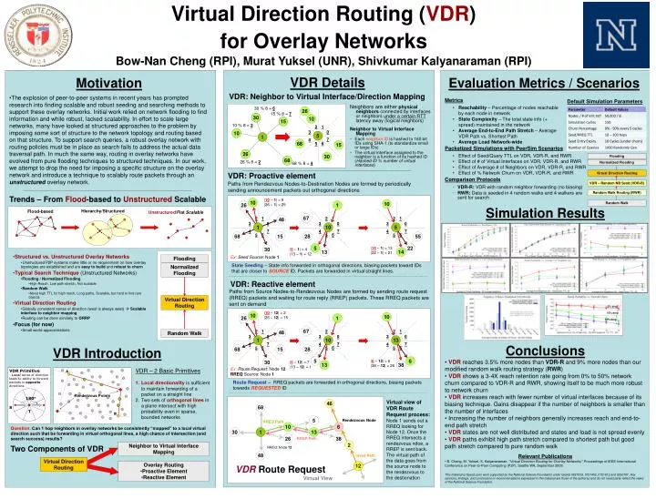
Virtual Direction Routing (VDR) for Overlay Networks Bow-Nan Cheng (RPI), Murat Yuksel (UNR), Shivkumar Kalyanaraman (RPI) Flooding Normalized Flooding 180o S T VDR Details • Motivation • The explosion of peer-to-peer systems in recent years has prompted research into finding scalable and robust seeding and searching methods to support these overlay networks. Initial work relied on network flooding to find information and while robust, lacked scalability. In effort to scale large networks, many have looked at structured approaches to the problem by imposing some sort of structure to the network topology and routing based on that structure. To support search queries, a robust overlay network with routing policies must be in place as search fails to address the actual data traversal path. In much the same way, routing in overlay networks have evolved from pure flooding techniques to structured techniques. In our work, we attempt to drop the need for imposing a specific structure on the overlay network and introduce a technique to scalably route packets through an unstructured overlay network. Evaluation Metrics / Scenarios VDR: Neighbor to Virtual Interface/Direction Mapping Metrics Default Simulation Parameters • Neighbors are either physical neighbors connected by interfaces or neighbors under a certain RTT latency away (logical neighbors) • Neighbor to Virtual Interface Mapping • Each neighbor ID is hashed to 160 bit IDs using SHA-1 (to standardize small or large IDs) • The virtual interface assigned to the neighbor is a function of its hashed ID (Hashed ID % number of virtual interfaces) • Reachability – Percentage of nodes reachable by each node in network • State Complexity – The total state info (+ spread) maintained in the network • Average End-to-End Path Stretch – Average VDR Path vs. Shortest Path • Average Load Network-wide 30 % 8 = 6 26 15 % 8 = 7 30 10 15 10 % 8 = 2 2 1 3 0 10 5 1 7 4 68 6 5 15 Packetized Simulations with PeerSim Scenarios 26 30 • Effect of Seed/Query TTL on VDR, VDR-R, and RWR • Effect of # of Virtual Interfaces on VDR, VDR-R, and RWR • Effect of Average # of Neighbors on VDR, VDR-R, and RWR • Effect of % Network Churn on VDR, VDR-R, and RWR Flooding 68 26 % 8 = 2 Normalized Flooding 68 % 8 = 4 VDR: Proactive element Virtual Direction Routing Comparison Protocols Paths from Rendezvous Nodes-to-Destination Nodes are formed by periodically sending announcement packets out orthogonal directions VDR – Random NB Send (VDR-R) • VDR-R: VDR with random neighbor forwarding (no biasing) • RWR: Data is seeded in 4 random walks and 4 walkers are sent for search Random Walk Routing (RWR) Trends – From Flood-based to Unstructured Scalable |10 – 1| = 9 |26 – 1| = 25 10 10 Random Walk 26 1 Simulation Results Hierarchy/Structured Flood-based Unstructured/Flat Scalable 67 2 1 2 1 48 2 1 3 0 3 0 3 0 5 1 10 7 7 7 4 4 4 6 6 6 5 55 68 5 15 28 5 5 22 30 |14 – 1| = 13 |22 – 1| = 21 |5 – 1| = 4 |13 – 1| = 12 13 14 • Structured vs. Unstructured Overlay Networks • Unstructured P2P systems make little or no requirement on how overlay topologies are established and are easy to build and robust to churn • Typical Search Technique (Unstructured Networks) • Flooding / Normalized Flooding • High Reach, Low path stretch, Not scalable • Random Walk • Need high TTL for high reach, Long paths, Scalable, but hard to find rare objects • Virtual Direction Routing • Globally consistent sense of direction (west is always west) Scalable interface to neighbor mapping • Routing can be done similarly to ORRP • Focus (for now) • Small world approximations Ex: Seed Source: Node 1 State Seeding – State info forwarded in orthogonal directions, biasing packets toward IDs that are closer to SOURCE ID. Packets are forwarded in virtual straight lines. VDR: Reactive element Paths from Source Nodes-to-Rendezvous Nodes are formed by sending route request (RREQ) packets and waiting for route reply (RREP) packets. These RREQ packets are sent on demand Virtual Direction Routing 5% drop |10 – 12| = 2 |26 – 12| = 15 15% drop 10 10 26 1 12% drop 67 2 1 2 1 48 2 1 Random Walk 3 0 3 0 3 0 13 1 10 7 7 7 4 4 4 • Conclusions • VDR reaches 3.5% more nodes than VDR-R and 9% more nodes than our modified random walk routing strategy (RWR) • VDR shows a 3-4X reach retention rate going from 0% to 50% network churn compared to VDR-R and RWR, showing itself to be much more robust to network churn • VDR increases reach with fewer number of virtual interfaces because of its biasing technique. Gains disappear if the number of neighbors is smaller than the number of interfaces • Increasing the number of neighbors generally increases reach and end-to-end path stretch • VDR states are not well distributed and states and load is not spread evenly • VDR paths exhibit high path stretch compared to shortest path but good path stretch compared to pure random walk VDR Introduction 6 6 6 5 68 5 15 28 5 5 6 30 |6 – 12| = 6 |38 – 12| = 26 |5 – 12| = 7 |13 – 12| = 1 13 38 Ex: Route Request: Node 12 RREQ Source: Node 1 VDR – 2 Basic Primitives • VDR Primitive • Local sense of direction • leads to ability to forward • packets in opposite • directions Rendezvous Points A • Local directionality is sufficient to maintain forwarding of a packet on a straight line • Two sets of orthogonal lines in a plane intersect with high probability even in sparse, bounded networks Route Request – RREQ packets are forwarded in orthogonal directions, biasing packets towards REQUESTED ID Virtual view of VDR Route Request process: Node 1 sends out a RREQ looking for Node 12. Once the RREQ intersects a rendezvous ndoe, a RREP is sent back. The virtual path of the data goes from the source node to the rendezvous to the destionation 46 68 B 5 Rendezvous Node RREQ Path 10 6 Question: Can 1 hop neighbors in overlay networks be consistently “mapped” to a local virtual direction such that be forwarding in virtual orthogonal lines, a high chance of intersection (and search success) results? 30 1 13 26 38 RREP Path 2 Neighbor to Virtual Interface Mapping Two Components of VDR RREQ: Node 12 48 • Relevant Publications • B. Cheng, M. Yuksel, S. Kalyanaraman, “Virtual Direction Routing for Overlay Networks," Proceedings of IEEE International Conference on Peer-to-Peer Computing (P2P), Seattle WA, September 2009. • This material is based upon work supported by the National Science Foundation under Grants 0627039, 0721452, 0721612 and 0230787. Any opinions, findings, and conclusions or recommendations expressed in this material are those of the author(s) and do not necessarily reflect the views of the National Science Foundation. Seed Path Virtual Direction Routing • Overlay Routing • Proactive Element • Reactive Element 12 VDR Route Request Virtual View