Download
1 / 5
50 likes | 209 Vues
Stave loading with Si-heaters at UniGe with jigs v-1. Maarten, Coralie , Franck, Didier. August 2011 . Work Preparation for the Loading Activities - Jigs. Handling frame inside the cradle. Grease mask added. Grease mask added. Half stave loaded. 2 nd added with 200µm gap.

E N D
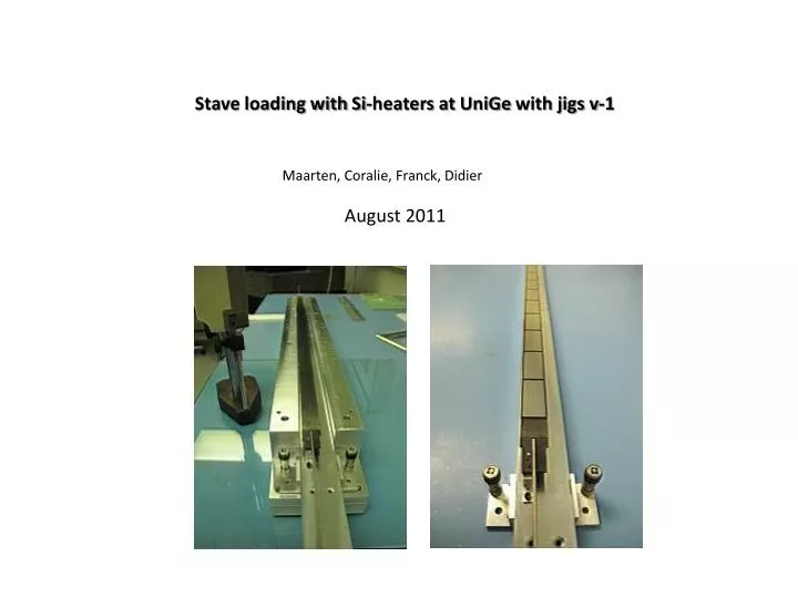
Stave loading with Si-heaters at UniGe with jigs v-1 Maarten, Coralie, Franck, Didier August 2011
Work Preparation for the Loading Activities - Jigs Handling frame inside the cradle Grease mask added Grease mask added Half stave loaded 2nd added with 200µm gap 1st Si-heater or digital module Wing handling to free the loading space Wing glue + adhesive hold in an envelope defined by the jig 2
Few comments about jigs v-1 • The adjustable feet (4 micrometric screws) are there to allow an average co-planarity between cradle blocks and the face plate. Warning: It can easily induce stress to stave! • 1st Si-heater will have to be glued with fast Araldite to give reference for the neighboring modules • Loading cradle is only compatible for Al-handling frame • It allows to load heaters and digital modules • The wing retract mechanism does not exist yet and need to be made for stave-1 • The wing gluing has also to be investigated – To be worked out
Cabling Equipment for Thermal Tests • Two Ag-silicon junction done thanks to electrical conductive glue and Cu-strips • 1.5 mm2 wire section used to allow powering individual modules • Thin cables and split in 4 wires for the PT100 readout • NB: • -The stiffness of the services was found not very compatible with the weakness and fragility of the loaded modules • - A Stress relief bar was designed and machined (thanks to Maarten & Gaby) to maintain all the cables above (49 in total leaving the stave) • - The handling frame v-1 (5x5 cm2 of CFRP) was made to hold the stave and Al-plate extenders were added for the pipe stress relieve • - An asymmetric cover was designed to protect the stave Warning: This cabling is not compatible for the thermal mock-up!