Download
1 / 30
320 likes | 633 Vues
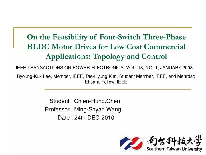
On the Feasibility of Four-Switch Three-Phase BLDC Motor Drives for Low Cost Commercial Applications: Topology and Control. IEEE TRANSACTIONS ON POWER ELECTRONICS, VOL. 18, NO. 1, JANUARY 2003. Byoung-Kuk Lee, Member, IEEE, Tae-Hyung Kim, Student Member, IEEE, and Mehrdad Ehsani, Fellow, IEEE.

E N D
On the Feasibility of Four-Switch Three-Phase BLDC Motor Drives for Low Cost Commercial Applications: Topology and Control IEEE TRANSACTIONS ON POWER ELECTRONICS, VOL. 18, NO. 1, JANUARY 2003 Byoung-Kuk Lee, Member, IEEE, Tae-Hyung Kim, Student Member, IEEE, and Mehrdad Ehsani, Fellow, IEEE Student : Chien-Hung,Chen Professor : Ming-Shyan,Wang Date : 24th-DEC-2010
Outline • Abstract • Introduction • A. Investigation of the Four-Switch Converter for BLDC Motor Drives • B. Operational Principle of Direct Current Controlled PWM • C. Current Regulation • D. Back EMF Compensated PWM Control Strategy • SIMULATION AND EXPERIMENTAL RESULTS • CONCLUSION • REFERENCES
Abstract • The main purpose of this paper is to describe a low cost four-switch brushless dc (BLDC) motor drive for commercial applications. For effective utilization of the developed system, a novel direct current controlled pwm scheme is designed and implemented to produce the desired dynamic and static speed–torque characteristics. Also, the feasibility of the four-switch converter is extended to two-phase BLDC motor drives and the six-switch converter for power factor correction and speed control. The operational principle of the four-switch BLDC motor drive and the developed control scheme are theoretically analyzed and the performance is demonstrated by both simulation and experimental results.
Introduction 〔1/4〕 VARIABLE-SPEED drives, employing a pulsewidth modulation (pwm) voltage-fed inverter, are being used for various purposes in consumer products and industrial applications. Although their technical advantages are generally acknowledged, researchers are becoming aware of their cost and are exploring the possibility of cost reduction. The cost reduction of variable-speed drives is accomplished by two approaches. One is the topological approach and the other is the control approach. From a topology point of view, minimum number of switches is required for the converter circuit. In the control approach, algorithms are designed and implemented in conjunction with a reduced component converter to produce the desired speed–torque characteristics. As a result, many different converter topologies have been developed and various pwm control strategies have been proposed to enhance the performance of the system [1]–[4].
Introduction 〔2/4〕 • Until now, the reduced part converters have been applied mainly to ac induction motor drives However, these days, the BLDC motor is attracting much interest, due to its high efficiency, high power factor, high torque, simple control, and lower maintenance [5], [6]. • we have been investigating the possibility of the reduced part converter for BLDC motor drives with advanced control techniques. Consequently, we found that one switch leg (two switches) in the conventional six-switch converter, as shown in Fig. 1, is redundant to drive a three-phase BLDC motorIt results in the possibility of thefour-switch configuration instead of the six switches, as shownin Fig. 2. Fig. 2. Proposed four-switch converter topology for three-phase BLDC motor. Fig. 1. Conventional six-switch three-phase BLDC motor drive systems
Introduction 〔3/4〕 • Compared with the four-switch converter for the induction motor [1], it is identical for the topology point of view. However, in the four-switch converter, the generation of 120 conducting current profiles is inherently difficult due to its limited voltage vectors. • This problem is well known as “asymmetric voltage pwm.” It means that conventional pwm schemes for the four-switch induction motor drive cannot be directly used for the BLDC motor drive. Therefore, in order to use the four-switch converter topology for the three-phase BLDC motor drive, a new control scheme should be developed. The solutions can be obtained from a modification of the conventional voltage controlled pwm strategies, such as the space vector pwm. equations for the transformation of voltage and current vectors,such as – and – – frames. As a result, the current control • block becomes much more complicated. Moreover, in order to handle the complicated calculations in one sampling period, a high-speed digital processor is also necessary, which increases the manufacturing cost. Therefore, for the low cost BLDC motor applications, voltage vector pwm schemes cannot be regarded as a good solution for cost effective purpose.
Introduction 〔4/4〕 • In this paper, we propose a novel pwm control technique based on the current controlled pwm method, instead of the voltage controlled pwm, which will be called “direct current controlled pwm.” The developed direct current controlled pwm method is not grounded on a bunch of equations, but on a keen and detailed observation of the overall operation, so that it dramatically reduces equations from the conventional control scheme and is simple to implement from the hardware and software points of view. Therefore, based on the direct current controlled pwm, the four-switch three-phase BLDC motor drive could be a good alternative to the conventional six-switch counterpart with respect to low cost and high performance. The theoretical operating principle of the four-switch converter for the three-phase BLDC motor drive and the proposed pwm control scheme are explained.
FOUR-SWITCH THREE-PHASE BLDC MOTOR DRIVE 〔1/11〕 A. Investigation of the Four-Switch Converter for BLDC Motor Drives A BLDC motor needs quasisquare current waveforms, which are synchronized with the back-EMF to generate constant output torque and have 120 degrees conduction and 60 degrees nonconducting regions. Also, at every instant only two phases are conducting and the other phase is inactive. However, as mentioned earlier, in the four-switch converter, the generation of 120 degrees conducting current profiles is inherently difficult. Thiscan be explained as follows:
FOUR-SWITCH THREE-PHASE BLDC MOTOR DRIVE 〔2/11〕 (a) (b) (d) (c) Fig. 3. Voltage vectors of four-switch converter. (a) (0, 0) vector, (b) (1, 1) vector, (c) (1, 0) vector, and (d) (0, 1) vector
FOUR-SWITCH THREE-PHASE BLDC MOTOR DRIVE 〔3/11〕 • In the four-switch configuration, there are four switching status as shown in Fig. 3, such as (0, 0), (0, 1), (1, 0), and (1, 1), in which the motor load is replaced by a resistive load and the switches are replaced by simple ideal switches. “0” means thatthe lower switch is turned on and “1” the upper switch is turned on. The two switches never turn on and off simultaneously. In the case of the six-switch converter, switching status (0, 0) and (1, 1) are regarded as zero-vectors, which cannot supply the dc-link voltage to the load, so that current cannot flow through the load. However, in the four-switch converter, one phase of • the motor is always connected to the midpoint of the dc-link capacitors, so that current is flowing even at the zero-vectors, as shown in Fig. 3(a) and (b). Moreover, in the case of (0, 1) and (1, 0), the phase which is connected to the midpoint of dc-link capacitors is uncontrolled and only the resultant current of the other two phases flow through this phase. If the load is ideally symmetric, there is no current in the (0, 1) and (1, 0) vectors.
FOUR-SWITCH THREE-PHASE BLDC MOTOR DRIVE 〔4/11〕 As a result of the operation using four switching vectors, one can depict the phase voltage or current waveforms as shown in Fig. 4. From Fig. 4, it is noted that obtaining the 120 conduction and a 60 nonconducting period current profile is inherently difficult based on the “asymmetric voltage pwm.” It means that conventional pwm schemes for the four-switch induction motor drives cannot be used directly for BLDC motor drives. Therefore, in order to use the four-switch converter topology for the BLDC motor drive, a new control scheme should be developed. Fig. 4. Voltage and current waveforms of four-switch converter based on four switching vectors
FOUR-SWITCH THREE-PHASE BLDC MOTOR DRIVE 〔5/11〕 B. Operational Principle of Direct Current Controlled PWM • From the motor point of view, even though the BLDC motor is supplied by the four-switch converter, ideal back-EMF of three-phase BLDC motor and the desired current profiles can be described as shown in Fig. 5. From the detailed investigation of the four-switch configuration and back-EMF and current profiles, we could come up with a pwm control strategy for the four-switch three-phase BLDC motor drives as follows: Fig. 5. Back EMF and current profile in the four-switch converter forthree-phase BLDC motor drives.
FOUR-SWITCH THREE-PHASE BLDC MOTOR DRIVE 〔6/11〕 • Under a balanced condition, the three-phase currents always satisfy the following condition: Then, (1) can be modified as • In the case of the ac induction motor drive, at any instant there are always three phase currents flowing through the load, such as
FOUR-SWITCH THREE-PHASE BLDC MOTOR DRIVE 〔7/11〕 However, in the case of the BLDC motor drive, (3) is not valid anymore. Note that in Fig. 5 phase A and B currents are only controllable and phase C is uncontrollable. According to the operating modes, one can derive the following current equations: Table I implies that due to the characteristics of the BLDC motor, such as two-phase, only two phases (four switches) needed to be controlled, not three phases. Therefore, based on Table I, one can develop a switching sequence using four switches as follows: TABLE I DETAILED CURRENT EQUATIONS ACCORDING TO THE OPERATING MODES
FOUR-SWITCH THREE-PHASE BLDC MOTOR DRIVE 〔8/11〕 As shown in Table II, the two-phase currents need to be directly controlled using the hysteresis current control method by four switches. Hence, it is called the direct current controlled pwm scheme. Based on the direct current controlled pwm, implementation of the switching sequence and current flow are depicted in Fig. 6. TABLE II SWITCHING SEQUENCES OF THE FOUR-SWITCH CONVERTER
FOUR-SWITCH THREE-PHASE BLDC MOTOR DRIVE 〔9/11〕 (f) (a) (e) (b) (d) (c) Fig. 6. Implementation of the direct current controlled pwm strategy. (a) Mode I (S ). (b) Mode II (S and S ). (c) Mode III (S ). (d) Mode IV (S ). (e) Mode V (S and S ). (f) Mode VI (S ).
FOUR-SWITCH THREE-PHASE BLDC MOTOR DRIVE 〔10/11〕 C. Current Regulation • Based on the switching sequences in Table II, the current regulation is actually performed by using hysteresis current control. The purpose of regulation is to shape quasisquare waveform with acceptable switching (ripple) band. The detailed waveforms • and switching sequences are described in Fig. 7. Fig. 7. Current regulation and detailed switching sequences.
FOUR-SWITCH THREE-PHASE BLDC MOTOR DRIVE 〔11/11〕 TABLE III VOLTAGE AND CURRENT EQUATIONS
SIMULATION AND EXPERIMENTAL RESULTS 〔1/6〕 • In order to verify the developed four-switch converter system, a computer simulation has been performed along with the conventional six-switch converter. As shown in Fig. 10(b), the 120 degrees conducting quasisquare shaped current profiles are successfully obtained using the developed direct current controlled pwm scheme, which are comparative with the ones • of conventional six-switch converter. (a) (b) Fig. 10. Phase currents waveforms. (a) Six-switch converter. (b) Four-switch converter.
SIMULATION AND EXPERIMENTAL RESULTS 〔2/6〕 • A prototype drive was designed and developed in the laboratory at Texas A&M University, as shown in the block diagram of Fig. 11. A 1HP Power Tec BLDC motor, rated 160 V and 3000 RPM, is used and a permanent magnet dc machine, rated 1 HP, 90 V, 1725 RPM, is used as a constant torque load. The load is changed by varying the value of the resistor . The entire system is controlled by the Texas Instrument (TI) • TMS320F243 digital signal processor. Fig. 11. Block diagram of experimental test bed.
SIMULATION AND EXPERIMENTAL RESULTS 〔3/6〕 • First of all, the conventional six-switch converter was built and tested. Fig. 12 shows the experimental phase current waveforms, using hysteresis current control with 160 V dc-link voltage. The current command is set at 2 A and every 20 kHz (50 s) pwm period the actual current is compared with the command value and determines which switches should be turned on or off. As explained earlier, in the six-switch converter, the three-phase BLDC motor is operated by quasisquare shaped current profile. Fig. 12. Experimental phase current waveforms of conventional six-switch converter (from top to bottom: Ia , Ib , Ic ; 5 A/div., 20 ms/div.).
SIMULATION AND EXPERIMENTAL RESULTS 〔4/6〕 • The performance of the developed four-switch converter for the three-phase BLDC motor with the direct current controlled pwm strategy is examined as follows: Fig. 13 shows the back-EMF problem of phase C, which was explained earlier in Section II-D. From Fig. 13 Fig. 13. Back-EMF problem of silent phases (from top to bottom: Ia , Ib , Ic ; 2 A/div., 50 ms/div.).
SIMULATION AND EXPERIMENTAL RESULTS 〔5/6〕 • In these cases, only positive current is sensed to generate pwm signal, so that the current distortion appears on the negative uncontrolled current. With the developed direct current pwm control strategy, considering back-EMF compensated solution, Fig. 14 shows the characteristics of the four-switch converter. As phases A and B are controlled • independently, one can obtain the successful current profile as shown in Fig. 14(a). Even though it contains more current ripplethan with the six-switch converter, it can be acceptable and also can be reduced by controlling the hysteresis band size. As shown in Fig. 14(a), as phases A and B are activated (modes II and IV), these phases are supplied by the full of dc-link voltage of and , so that in the one pwm period (50 s), the current is increased more than the other operating modes. Moreover, independent control of phases A and B results in current ripple in phase C during the silent periods, which is the difference between the phase A and phase B currents. The detailed switching signal waveforms can be observed from Fig. 14(b) and (c). As shown in Fig. 14(c), it is noted that the switching signals of and are not identical. It means that the phase A and B currents are controlled independently to prevent the effect of back-EMF of phase C during modes II and V.
SIMULATION AND EXPERIMENTAL RESULTS 〔6/6〕 (a) (b) (c) Fig. 14. Experimental voltage and current waveforms of the developed four-switch three-phase BLDC motor drives. (a) Phase current profiles (50 ms/div., 2 A/div.). (b) Phase A and B currents with the gating signal of S1 and S2 (from top to bottom: Ia , Ib , S1 , S4 ; 10 V/div., 2 A/div., 20 ms/div.). (c) Expanded waveforms of (b) (10 V/div., 2 A/div., 5 ms/div.).
PERFORMANCE COMPARISON 〔1/3〕 • The overall operating modes of the four-switch BLDC drive are divided into six modes, as show in Fig. 6. According to the voltage utilization, these modes are classified into two groups: one is full dc-link voltage utilization (modes II and V) and other is half dc-link voltage (modes I, III, IV, and VI). This irregular voltage utilization distinguishes the four-switch converter from the six-switch one in terms of current dynamics, slow , and speed limitation: During the half dc-link voltage period, the motor phases are energized by half value ( ) of the full dc-link voltage (2 ), so that it produces the slower . Therefore, in a pwm period, the rate of current incensement is less than the full dc-link voltage period. This irregular current shape can cause torque ripple, but it can be controllable by adjusting hysteresis band size and fundamentally do not affect any changes in the operation of the BLDC motor drive, such as low speed and four quadrant operations.
PERFORMANCE COMPARISON 〔2/3〕 • The other affect of the irregular voltage utilization is speed limitation. In case of the conventional six-switch converter, all motor phases are excited by the full dc voltage. However, in case of the four-switch converter, mainly only half dc voltage is utilized through all operations. This voltage utilization makes the four-switch BLDC motor drive have speed limitation. The relation between dc-link voltage, back-EMF, and speed can be • observed as • As shown in (4), the operating speed range is determined by the back EMF and dc-link voltage. In case of the four-switch converter, the dc-link voltage is half of the six-switch one, so that a BLDC motor can be operated by the half speed.
PERFORMANCE COMPARISON 〔3/3〕 • The above-mentioned two problems, such as slow and speed limitation, are the inherent characteristics and main drawbacks of the four-switch configuration. However, those problems can be overcome in conjugation with voltage-doublers as • shown in Fig. 15. Using the half-bridge configuration of diode rectifier, one can obtain double value of the dc voltage from the same ac source. Also if the front-end is replaced with active power semiconductor switches, the dc-link voltage can be • controlled to the desired value. The half-bridge diode rectifier can be a low cost and effective solution; otherwise the active voltage-doubler has additional advantage, such as unity power factor correction.
CONCLUSION • In this paper, the four-switch converter topology is studied to provide a possibility for the realization of low cost and high performance three-phase BLDC motor drive system. From the observation, one should note that the development of the proper pwm control strategy should be accompanied with the reduced parts converter. As a solution, we propose the direct current controlled pwm and examine the performance. With the developed control scheme, it is expected that the proposed system can be widely used in commercial applications with a reduced system cost.
REFERENCES [1] H.W. Van Der Broeck and J. D. VanWyk, “A comparative investigation of a three-phase induction machine drive with a component minimized voltage-fed inverter under different control options,” IEEE Trans. Ind. Applicat., vol. 20, pp. 309–320, Mar./Apr. 1984. [2] F. Blaabjerg, D. O. Neacsu, and J. K. Pedersen, “Adaptive SVM to compensate dc-link voltage ripple for four-switch three-phase voltagesource inverter,” IEEE Trans. Power Electron., vol. 14, pp. 743–752, July 1999. [3] G. T. Kim and T. A. Lipo, “VSI-PWM rectifier/inverter system with a reduced switch count,” IEEE Trans. Ind. Applicat., vol. 32, pp. 1331–1337, Nov./Dec. 1996. [4] J. I. Itoh and K. Fujita, “Novel unity power factor circuits using zerovector control for single-phase input systems,” IEEE Trans. Power Electron., vol. 15, pp. 36–43, Jan. 2000. [5] P. Pillay and P. Freere, “Literature survey of permanent magnet ac motors and drives,” in Proc. IEEE IAS Rec., 1989, pp. 74–84. [6] J. R. Hendershot and T. J. E. Miller, Design of Brushless Permanent-Magnet Motors. Oxford, UK: Oxford Science, 1994.