Download
1 / 26
260 likes | 679 Vues
Trigger/DAQ/DCS. TDMT on behalf of the Trigger/DAQ System. LVL1: Introduction. O (1M) RPC/TGC channels. ~7000 calorimeter trigger towers. Muon trigger. Calorimeter trigger. Muon Barrel Trigger. Muon End-cap Trigger. Pre-Processor (analogue E T ). Muon-CTP Interface (MUCTPI).

E N D
Trigger/DAQ/DCS TDMT on behalf of the Trigger/DAQ System
LVL1: Introduction O(1M) RPC/TGC channels ~7000 calorimeter trigger towers Muon trigger Calorimeter trigger Muon Barrel Trigger Muon End-cap Trigger Pre-Processor (analogue ET) Muon-CTP Interface (MUCTPI) Jet / energy-sum Processor Cluster Processor (e/g, t/h) Central Trigger Processor (CTP) Timing, Trigger, Control (TTC) ROD_BUSY LTP Timing, Trigger, Control (TTC) ROD_BUSY LTP
LVL1: Calorimeter Trigger • Preprocessor • Preprocessor Module is being assembled and will be debugged in March • essential for slice tests • enough existing ASICs and MCMs work well enough to do slice tests • ASIC resubmitted with minor design faults corrected • final version expected back imminently • MCM yield is currently lower than expected, due to surface finish and faulty ASICs • must understand surface finish problem • must test ASIC dies more thoroughly before mounting them
LVL1: Calorimeter Trigger • Cluster Processor • Cluster Processor Module design updated to improve timing margins; now being made • problems with badly made boards now hopefully solved by finding "one-stop shop" firms with better instrumentation and QA • Jet/Energy-sum Processor • Jet/Energy Module re-designed to use Virtex-II FPGA; now being made • Common Modules: • Common Merger Module design is essentially final; no big changes needed • Readout Driver full-specification design is being laid out • Handles readout to DAQ from all types of trigger modules • Also handles RoIs to level-2 • Each ROD reads out a full crate of trigger modules
LVL1: Calorimeter Trigger • Have tested analogue receiver/monitor modules from Pittsburgh and been in close contact with them • Simulated LAr and TileCal signals sent via receiver to Preprocessor analogue input circuit • TileCal signals sent to receiver in test-beam • Further tests have been done by TileCal group • Receiver circuit has been modified to handle saturated pulses better • Discussions continue on use of LAr and TileCal calibration signals for energy and timing calibration of calorimeter trigger
LVL1: Muon Trigger On-detector electronics Barrel and endcap systems successfully operated in 25 ns test-beam last September — endcap chain included MUCTPI and CTPD RPC Off-detector
LVL1: Muon Trigger MDT Off-detector TGC Near-detector On-detector electronics HPT SSW
LVL1: Muon Trigger • Work going on to produce final version of all parts of on-detector system in time for test-beam this summer • “Slave Board” ASIC for endcap trigger • Revised version recently submitted • “Coincidence Matrix” ASIC for barrel trigger • Design revisions ongoing — hope to submit in April • Final version of “PAD” boards for barrel trigger • Prototypes of revised design being assembled • Much design work still to be completed, including: • Many variants of “PS” boards for endcap trigger (connectivity depends on detector region) • Off-detector electronics • Has been given lower priority than on-detector electronics since it is not critical for the detector integration/installation schedule
LVL1: Muon Trigger • Production quantities of on-detector barrel electronics needed as soon as possible for integration with detectors • Pre-production of barrel “Splitter” boards already available • Main production in preparation (orders for components, etc ongoing) • Production of barrel “Pad” boards will start as soon as possible • After completion of tendering process • After checking of prototypes • Schedule for production (and QA testing) of on-detector electronics for both barrel and endcap triggers is tight
LVL1: Central Trigger Processor CTP crate: • COM_backplane: produced • PIT/CAL_backplane: produced • CTP_MON: tested successfully • CTP_MI: produced recently (see photo) • CTP_CORE: under design • CTP_IN: under design • CTP_OUT: under design • CTP_CAL: to be designed later Plan: • Prototype with one module each • no CTP_CAL • CTP_CORE w/ reduced functionality • Lab-tests: Jul-Aug 2004 • Testbeam: 25 ns period Sep 2004 • Final CTP: beginning of 2005 CTP_MI
LVL1: Central Trigger Processor Trigger Menu : the collection of the (256) Trigger Items, formed from combinations of (256) Trigger Conditions on the (160) Trigger Inputs. LUT CAM Mask Prescaling Priority 160 256 256 Trigger Conditions TriggerInputs Trigger Items programmable programmable programmable 160 inputs at any time selected from > 160 on input boards Decode incoming multiplicities, map onto 256 Trigger Conditions Each trigger item can be a combination of ALL 256 trigger conditions Compared to TDR: • more trigger items (TDR limit was only 96) • programmable LUTs/CAM (no FPGA re-configuration) • larger flexibility to construct Trigger items from all inputs
HLT/DAQ/Controls Some highlights and examples of ongoing work
HLT, DAQ and Controls TDR Several meetings took place with the LHCC referees since the last Plenary, presentations and summaries are on the Web A very major milestone for ATLAS is the positive conclusion of the HLT/DAQ/Controls TDR review process at the end of 2003 CERN/LHCC 2003-069/G-067: ‘The LHCC finds both the technology adopted and the procedures proposed for the ATLAS HLT/DAQ/DCS to be adequate to achieve the physics goals stated in the Technical Proposal, and congratulates the ATLAS Collaboration on the quality of the work presented in the TDR.’ ‘The LHCC therefore recommends general approval of the ATLAS HLT/DAQ/DCS TDR.’
Plans for large-scale test (control) 1 EB Segment 1 Online Infrastructure Segment 1 pROS 1 DFM 5 SFIs 4 SFOs 1 node: Start up Servers Monitoring factory Servers 1 Global Segment for L2 Sub-farms 1 Global ROS Segment 1 Global Segment for EF Sub-farms 5 individual L2 sub-farm segments 32 nodes per sub farm 1 application per node: Sub-farm controller(1) L2SV(1), L2PU(30) 8 Sub detector segments 5 EF sub-farm segments 32 nodes per sub farm:Controller (1), EF(31) running 1 EFD + 4PTs each Legend: 16 nodes per detector: Controller (1), ROS (15) Node running a controller: Node running one or more applications Numbers for similar configurations will vary depending on each other for a total of ~ 250 nodes
Example of work in PESA group mFast • mFast latency reduced by 60 ms thanks to the new data-access schema: • fewer MDT hits to handle and process • RPC and MDT data preparation improved: • total data prep time ~ 800 ms • data preparation takes the same amount of CPU time of mFast Total The muon selection latency at Level-2 is now ok!
Unified Monitoring Scheme (for test-beam) Readout System ALARMS & Status Displ. Intelligent Monitoring Intelligent Monitoring ROB,ROS,SFI,SFO,… Mon Mon Mon Mon Mon Mon Mon Mon Mon Mon Mon Mon Mon Mon Mon Display Shift Crew Display Experts Display Experts Gatherer Subd. Slow Ctrl. DBS LVL1 Var. Ref. DBS Gatherer Subd. LVL2/EF Slow Control Tier 0 Monitoring DBS Archiver Archiver Gatherer Rec Calibration FARM Data Qual. DBS Data Quelity Assessment Gatherer Calib. Dynamic Allocation Of Links online Var. Conf. DBS
HLT Development & Integration Testbeds • LVL2 alone • no algs Jan04 DF-06-00->DF 06-02 , Online 20 • EF alone • no algs Jan-Feb04 nightly*->DF 06-02 , Online 20 • HLT (LVL2+EF) Integrated • no algs Jan-Feb04 nightly*->DF 06-02 , Online 20 • Large Scale tests • Starts ~1st March 04 • No algorithms • Testbeam preparations • In progress • Testbeds with algorithms • Begin in March with Offline R8
S-Links I/O path for Read-Out System PCI bus ROBIN GbE • In TDR (30 June 2003): • “The optimisation of the ROS architecture will be the subject of post-TDR studies” using a Read-Out Buffer (ROBIN) prototype implementing bus-based (PCI) and switched-based (GEth) I/O paths • Schedule and milestones to match ATLAS commissioning • ROBIN Final Design Review completed LHCC 31.05.04 • Final decision on ROS Input/Output path EB 31.12.03
I/O path for Read-Out System NIC ROBIN ROBIN ROBIN PCI bus S-Links Increased scalability if/when needed PCI bus ROBIN GbE GbEthernet L2 & Event Builder Networks • On 11 Dec 2003, TDAQ decision was made:Bus-Based (BB) with Switch-Based (SB) as option for increased scalability • ROBIN : 3 Slink input - PCI and GEth output • Max input retaining max output functionality • High potential for scalability and upgrades • The baseline implementation of the ROS would be BB with an upgrade path to combined BB and SB I/O or only SB I/O for future upgrades. Full assessment of the potential of the SB Read-Out will be done as soon as possible (planning in preparation), so as to be ready with a viable upgrade if and when needed.
ROBin schedule • Measurements on existing prototype continuing: • Meeting required performance for final system • Schedule for final module • FDR schedule detailed : on time for LHCC milestone May 2004 • Final Protoypes Sep 2004 • Tendering starts Sep 2004 • PRR Oct 2004 • Production starts Feb 2005 • Production completed May 2005
Software releases and testbeam • DAQ release (targeted to TB-2004) • LHCC milestone (see TDR) 30.04.04 • Online Software release 29.02.04 • Dataflow release 31.03.04 • Status • Online Software release 00-21-00 done on 09.02.04 • Dataflow release (including now ROD-Crate DAQ and EF Dataflow) 00-07-00 01.03.04 • New HLT Release 13.02.04 • Release and software integration testing • Continuously done in our HLT/DAQ test-beds • Major testing step: large scale scalability test on 250 PCs starting next Monday for 4 weeks • Detector integration for TB-2004 • Global planning being finalized • Pre-testbeam lab setup in Bdg 40, 5th floor - Integration at RCD started
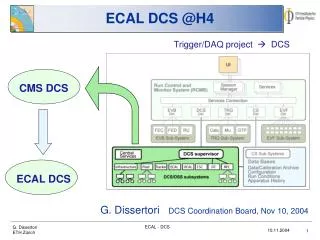
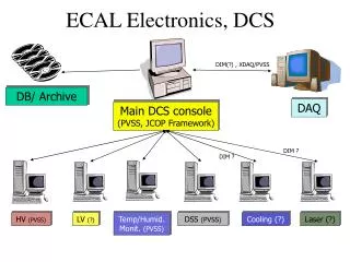
DCS Subdetectors • Individual meetings with each subdetector have been held to: • Agree on deliverables provided by the central DCS team to subdetector groups with the timescale • Define and document a DCS Baseline • The point of connection between the subdetector DCS and the central DCS is the Subdetector Control Station (SCS) • Subdetectors are responsible for everything towards the detector • Central DCS is responsible for the items towards the control room
Central DCS Deliverables • SCADA software PVSS and JCOP Framework • Connection software to DAQ (DDC) • Tools and libraries for front-end read-out of standard devices • All functions needed for operations from the control room • Supervision of common experimental infrastructure • Connection to Detector Safety System (DSS) • Information exchange with the CERN services • Information exchange with the LHC machine
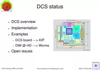
Subdetector responsibilities • The subdetector groups are responsible for all applications in the SCS and for all HW and SW in the SCS and the Local Control Stations (LCS) below • The CAN/ELMB hardware will be procured centrally (on subdetector budget) • CAN/PCI interface (commercial, selected) • ELMB (in production) • CAN Power Supervisor (being prototyped) • CAN cables (to be defined by subdetector)
Issues • Conditions DB: ATLAS plans? • For testbeam 2004: Lisbon API • Configuration DB: ATLAS plans? • Changes in interaction with DAQ Run Control? • Workspace for subdetector groups • Commissioning and debugging in US(A)15 and (where) on surface? • Where are the SCS located? • DCS Network • Security (remote) Accessibility Summary: • No major problems discovered • Some issues to tackle • DCS Baseline is defined and documented • See http://agenda.cern.ch/displayLevel.php?fid=3l89