Download
1 / 26
320 likes | 807 Vues
Chapter. 22. Elevations. Objectives. List features that should be included on an exterior elevation. Describe the placement of walls, windows, and doors on an elevation. Explain how to show roof features on an elevation. Identify the dimensions commonly shown on elevations.

E N D
Chapter 22 Elevations
Objectives • List features that should be included on an exterior elevation. • Describe the placement of walls, windows, and doors on an elevation. • Explain how to show roof features on an elevation. • Identify the dimensions commonly shown on elevations. • Draw an exterior elevation that demonstrates proper techniques.
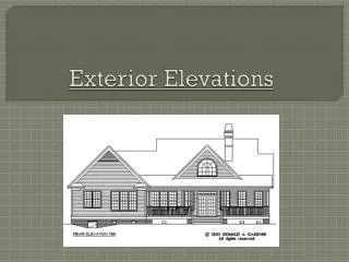
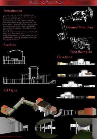
Introduction to Elevations • Elevation • Orthographic projection drawing of one side of building • Gives vertical dimensions • Shows exterior materials
Elevation Identification • Four elevations—one for each side of house • Identified by structure side or compass points
Employability • Coping with stress • Changes can cause stress • Stress can affect work performance • Understand cause of your stress, then think about ways to handle it
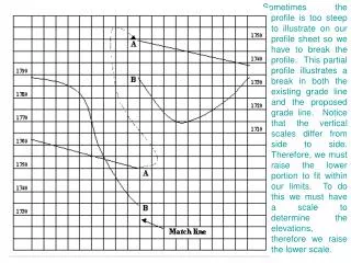
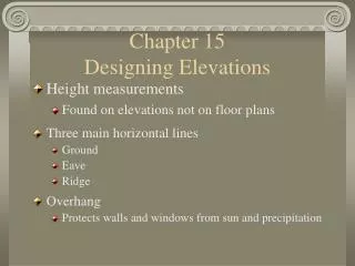
Grade Lines, Floors, and Ceilings • Grade line is reference point for most elevations • Plot plan shows the existing grade • Draw all features below grade as hidden lines • Top of foundation wall must be at least 8" above grade
Floor-to-Ceiling Height • Two methods of representing floor-to-ceiling height • Indicate distance from finished floor to finished ceiling • Show construction dimension
Walls, Windows, and Doors • Show visible wall corners as object lines • Draw a wall section to identify vertical heights needed for drawing • Include windows and doors that are visible on exterior wall • Tops of windows and doors are usually 6'-10" from the top of the subfloor
Architecture Green • Sustainable exteriors • Eco-friendly stucco made entirely from natural limestone • Nontoxic paint • Sustainable alternative finishes save money in the long run and preserve environment
Roof Features • Shown on an elevation drawing • Roof style and pitch • Chimney height and size • Draw gable ends first to determine roof height—highest section first • Show chimney flashing, roof covering material, and gable ventilators
Frequently used symbols: Roof pitch symbol Exterior materials Window swing symbols Cutting-plane lines Dimensions, Notes, Symbols • Dimensions on elevations are mainly height dimensions • Notes provide additional information
Manual Drafting: Elevations 1. Draw a section through the wall to be represented by the elevation. Section should be 1/4" = 1'-0" scale. Draw a section for each different type of wall. 2. Place floor plan above space where elevations are to be drawn.
Manual Drafting: Elevations • Steps 1 and 2
Manual Drafting: Elevations 3. Project heights of features on section drawing to space where elevation is to be drawn. 4. Project the features from the floor plan to the space where the elevation is to be drawn.
Manual Drafting: Elevations • Steps 3 and 4 Insert Figure 22-8
Manual Drafting: Elevations 5. Darken each feature and remove construction lines. Check overall design. 6. Add details such as railings, window muntins, trim, window wells, and gable ventilators. Check manufacturer’s literature.
Manual Drafting: Elevations • Steps 5 and 6
Manual Drafting: Elevations 7. Add dimensions, notes, and symbols. Draw material symbols last. 8. Check drawing for completeness. 9. Add title block and scale.
Manual Drafting: Elevations • Steps 7, 8, and 9
CADD: Elevations 1. Draw typical wall section to provide height measurements. Draw objects for section at actual size. 2. Place copy of floor plan above space where elevation will be drawn. Place side of floor plan that will be shown in elevation facing area where elevation will be drawn.
CADD: Elevations 3. Project features to be drawn on elevation from floor plan. Project one or more elements at a time. Projection lines should be on separate layer. 4. Locate foundation wall, footings, and grade line heights on elevation. These will be hidden lines except for grade line. Use separate layers.
CADD: Elevations 5. Locate wall height and roof lines on elevation. Draw exterior walls above grade and roof. Exterior wall lines should have their own layer. 6. Locate height of windows, doors, and other features. Use symbols library for complex symbols.
CADD: Elevations 7. Add dimensions and notes. 8. Add material symbols (hatch patterns). 9. Add scale and title. 10. Hide or turn off layer(s) containing floor plan copy and wall section. 11. Follow same procedure to create elevations for remaining sides of house.
Advanced CADD • Some advanced CADD software drafts basic lines of exterior elevations automatically • When using 3D coordinates or advanced CADD features, display each elevation view as an orthographic view or projection before adding dimensions and notes • Turn off perspective projection