Download
1 / 21
290 likes | 993 Vues
Designing a simple Electronic Timer Circuit using Crocodile Clips Software. Log-on to your computer Open up DT File To install Crocodile Technology on your computer screen, Click-on Crocodile Technology to open software. Tool Bar with five different component libraries

E N D
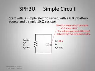
Designing a simple Electronic Timer Circuit using Crocodile Clips Software • Log-on to your computer • Open up DT File • To install Crocodile Technology on your computer screen, Click-on Crocodile Technology to open software
Tool Bar with five different component libraries • Analogue electronic components • Electronic Picture components • Digital electronic components • Mechanical and • Electro-Mechanical components • Flow chart components
Assembling your timer circuit • From the components toolbar, click-on Analogue Components • On the analogue toolbar, move the cursor along each window until the words Analogue Integrated Components appears. Click-on this window • The tool bar will have changed showing two components. One will show the numbers 555 in the middle. Click-on this window • The tool bar will have changed showing four different arrangements for the component 555. Click-on the first and hold whilst dragging it onto the blank screen area. Place it in the middle by releasing the mouse button.
Well done, you have now placed your first electronic component in position. If you have not placed the component in the correct position, click-on the component again and relocate by dragging and releasing in new position
Deleting unwanted components • Deleting components • Components can be removed by selecting and pressing delete on your keyboard • Or you can select the Crocodile on the menu bar and move it towards the component and when its jaw opens on the chosen component, click to see it EAT it up!
Adding Picture Components • Click-on the Picture Components on the Components Toolbar • The toolbar above will now have changed to show Pictures of the actual components. • Move along the components and select a Resistor • and drag it on to the screen area and place in the position shown. Repeat this for the second resistor.
Again from the Picture Components select another Resistor • and drag it onto the screen area, place it to the right of the 555 Timer and connect it to the line marked with a number 3. • Next select a coloured LED of your choice and connect it to the last Resistor placed.
Again from the Picture Component toolbar, select a Red Push Switch and drag carefully into the position shown.
Return to the Analogue Electronic Components toolbar and move along the tool bar windows until the cursor indicates Passive Components and select. • The tool bar will change to another selection of components. Move the cursor along the row of components until you find Electrolytic Capacitors and select. • The tool bar will change again showing a selection of capacitors. Select an Electrolytic Capacitor with the plus sign at the top and drag carefully into position to the left of the switch.
Your screen area should now look like this The value of the capacitor can be changed by selecting the capacitor and altering the figures in this box
Return to the Picture Components tool bar and select a 9V Battery, • drag into position below the two resistors. The top of the battery is also below the capacitor and red push switch previously located. • All the components for the circuit have now been selected for connecting together in the circuit.
Your screen area should now look like this Battery position guidelines
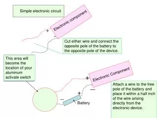
Making Circuit Connections • The first components to be connected together are the two resistors and the battery. • Move the mouse cursor until it touches the positive battery terminal and press the Select on the mouse. • The arrow cursor will change to a symbol which looks like a roll of tape. Keeping the button pressed, drag the ‘Roll of Tape’ towards the resistor until it touches the end of the wire and the tape changes to a dot. This indicates it has made the connection successfully. • Release the select button and the line drawn should remain in position. • Try to repeat this procedure for other connections. • To change directions using the connecting wire can be achieved automatically by simply moving the mouse at right angles.
Connections continued:- • Should a circle appear with a line across it, when you try to make a connection, this means it is not a suitable connecting position and you will need to select another position. • Connecting wires should not be dragged across components, otherwise a connection will not be permitted and the connection cannot be made. • Have a try to see if you can make all the remaining connections illustrated until the final diagram.
Replacing Damaged Components • When the final connections are being made, it is possible some of the components will appear to BLOW-UP! • Do not worry, continue with all the connections until they are complete. • To replace the damaged components, simply select the component using mouse select, the component will appear with a dotted line border, press the delete key. Alternatively you can eat it up with the crocodile. • A decision box will appear, asking if you wish to replace the damaged component, click yes. The component will repair itself.
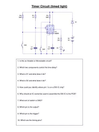
Operating the Timer Circuit • Once the circuit is complete, CHECK that all the connections and component values are correct. • To operate the timer circuit, simply move the mouse cursor to the Red Switch Button and click on the Red Top on the switch. • The button will appear to be pressed in and the Red LED will light up for a period of time and then stop. • Repeat this operation and notice what is occurring to each side of the capacitor. What do you think is happening to the Capacitor? • How can the time period the LED is lit, be altered to operate for a longer/shorter period?
You have now completed designing your first electronic circuit using Electronic Communications Technology ECT There are many software packages available which can used to help learn about designing, modelling, programming, computer control and making interesting electronic products. Learning about Electronics is exciting and using ECT can make it more fun than reading books.