Download
1 / 41

E N D
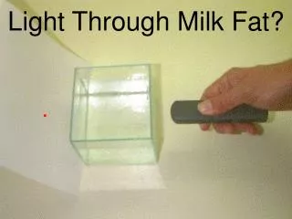
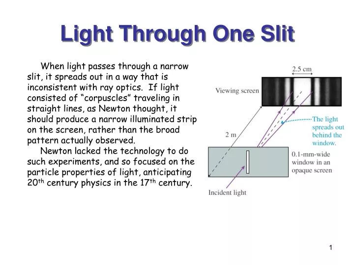
Light Through One Slit When light passes through a narrow slit, it spreads out in a way that is inconsistent with ray optics. If light consisted of “corpuscles” traveling in straight lines, as Newton thought, it should produce a narrow illuminated strip on the screen, rather than the broad pattern actually observed. Newton lacked the technology to do such experiments, and so focused on the particle properties of light, anticipating 20th century physics in the 17th century.
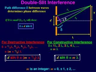
Two-Slit Interference There are an alternating pattern of bright and dark “fringes” that arise from the interference of light passing through the two slits.
Analyzing 2-Slit Interference Bright fringes Dark fringes
Example: Double Slit Interference of a Laser Beam Light from a helium-neon laser (l = 633 nm) illuminates two slits placed 0.40 mm apart. A viewing screen is placed 2.0 m behind the slits. What are the distances Dy2 between the two m=2 bright fringes and Dy’2 between the two m=2 dark fringes?
Example: Measuring the Wavelength of Light A screen is placed 1.0 m behind a pair of slits, which are spaced 0.30 mm apart. When this system is illuminated by a certain frequency of monochromatic light, ten bright fringes are found to span a distance of 1.65 cm on the screen. What is the wavelength of the light?
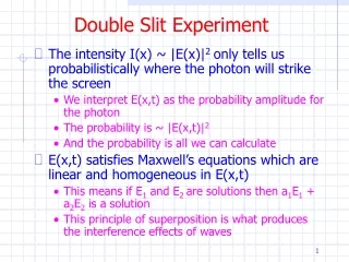
Intensity of theInterference Pattern Problem: Observed fringes are not of equal brightness. ( see Lecture #7)
Two Slit Interference (again) Choose the phase of the1st slit at the screen at t=0 to be 0. Then: ( see Lecture #7)
I3/I1 d (radians) Three Slit Interference Choose the phase of the 1st slit at the screen at t=0 to be 0. Then: ( see Lecture #7)
IN/I1 d (radians) 1 0.8 N = 2 0.6 IN/I1N2 0.4 3 4 0.2 5 100 - - - 3 2 1 0 1 2 3 d (radians) Multi-Slit Interference N=5 ( see Lecture #7)
2 IN/I1 3 4 N = 5 p d (radians) Phasors and Slits N = 6 One can think of the light amplitudes from adjoiningslits as Phasors. Adjacent phasors have a relative phase angle d = k d sin q. When d=0, the phasors add in a straight line. But there are some values of q for which the phasors add to zero, e.g., d=600. The more slits are used, the more ways there are that the corresponding phasors can add to zero, “tacking” the interference pattern to zero at more and more places between 0<d<p. # of zeroes = N-1 http://www.ptolemy.eecs.berkeley.edu/eecs20/berkeley/phasors/demo/phasors.html http://en.wikipedia.org/wiki/Phasor_%28physics%29
dq d (radians) The Diffraction Grating N = 100 The integer m is called the order of diffraction.
Unlike the angles in double-slit interference, the angles of constructive interference from a diffraction grating are not small angles. • The wave amplitude at the points of constructive interference is N a because N waves of amplitude a combine in phase. • Where I1 is the intensity of the wave from a single slit. • The width of the bright fringes must be proportional to 1/N.
White Light Light with l1=400 nm and l2=700 nm. A Grating Spectroscope Light can be dispersed by wavelength using a diffraction grating. A grating spectroscope provides a way of making precise measurements of wavelength by noting the angular positions at which bright fringes occur. If photographic plates or CCDs are used to make a more permanent record, the device is called a grating spectrograph. Atoms in a low pressure electrical discharge produce light with characteristic wavelengths that can be identified with a spectrograph.
Grating Interference Patterns Monochromatic light produces one fringe for each value of m. Light containing more than one wavelength produces one fringe for each value of m>0 for each wavelength.
Example: Measuring Wavelengths Emitted by Sodium Light from a sodium lamp passes through a diffraction grating having 1000 slits per millimeter. The interference pattern is viewed on a screen 1.000 m behind the grating. Two bright yellow fringes are visible at distances of 72.88 cm and 73.00 cm from the central maximum. Assuming that m=1, what are the wavelengths of these two fringes?
Reflection Gratings The mirror-like surfaces can also be tilted to deliver more light intensity to average angle of the m=1 spectrum. This is called “blazing”. Interestingly, some of the most colorful bird feathers and insect shells are, in effect, blazed reflection gratings. A grating may also be arranged to reflect light rather than transmit it. Ruling parallel grooves in a mirror-like metal surface produces such a grating. NASA uses reflection gratings that are also curved mirrors,
“Superluminal” Quasar t=0 Saturn 16 light years Mars The Sun t=1 year Radio Telescope Arrays A line of parabolicdish radio receiversbehaves like a diffraction grating in reverse, giving high-precision locations of radio sources in the sky. Processing the data with varying phases between dish signals produces dramatic high resolution images of the universe as viewed with radio waves.
Clicker Question 1 White light passes through a diffraction grating and forms rainbow patterns on a screen behind the grating. For each rainbow: • The red side is on the left, and the violet side is on the right; • The red side is on the right, and the violet side is on the left; • The red side is closest to the center of the screen, and the violet side is farthest from the center of the screen; • The red side is farthest from the center of the screen, and the violet side is closest to the center of the screen.
Christian Huygens (1629 - 1695) Huygens’ Principle The Dutch scientist Christian Huygens, a contemporary of Newton, proposed Huygens’ Principle, a geometrical way of understanding the behavior of light waves. • Huygens Principle: Consider a wave front of light: • Each point on the wave front is a new source of a spherical wavelet that spreads out spherically at wave speed. • At some later time, the new wave front is the surface that is tangent to all of the wavelets.
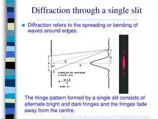
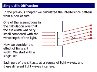
Single Slit Diffraction when light goes through a narrow slit, it spreads out to form a diffraction pattern. Now, we want to understand this behavior in more detail.
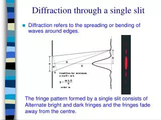
Analyzing Single Slit Diffraction For an open slit of width a, subdivide the opening into segments and imagine a Huygens wavelet originating from the center of each segment. The wavelets going forward (q=0) all travel the same distance to the screen and interfere constructively to produce the central maximum. Now consider the wavelets going at an angle such that l = a sin q @a q. The wavelet pair (1, 2) has a path length difference Dr12 = l/2, and therefore will cancel. The same is true of wavelet pairs (3,4), (5,6), etc. Moreover, if the aperture is divided into p sub-parts, this procedure can be applied to each sub-part. This procedure locates all of the dark fringes. ±
1.2 cm Example: Diffraction of a laser through a slit Light from a helium-neon laser (l = 633 nm) passes through a narrow slit and is seen on a screen 2.0 m behind the slit. The first minimum of the diffraction pattern is observed to be located 1.2 cm from the central maximum. How wide is the slit?
-y1 y1 y2 y3 0 Width of a Single-SlitDiffraction Pattern w
l = 633 nm a = 0.25 mm 0.5 mm 1 mm 2 mm Blowup q (radians) Diffraction Patterns The narrower the slit opening a, the broader is the diffraction pattern.
Clicker Question 1 l1 l2 Two single slit diffraction patterns are shown. The distance from the slit to the screen is the same in both cases. Which of the following could be true? (a) The slit width a is the same for both; l1>l2. (b) The slit width a is the same for both; l1<l2. (c) The wavelength is the same for both; width a1<a2. (d) The slit width and wavelength is the same for both; p1<p2. (e) The slit width and wavelength is the same for both; p1>p2.
Circular Apertures When light passes through a circular aperture instead of a vertical slit, the diffraction pattern is modified by the 2D geometry. The minima occur at about 1.22l/D instead of l/d. Otherwise the behavior is the same, including the spread of the diffraction pattern with decreasing aperture.
The Rayleigh Criterion The Rayleigh Resolution Criterion says that the minimum separation to separate two objects is to have the diffraction peak of one at the diffraction minimum of the other, i.e., Dq = 1.22 l/D. Example: The Hubble Space Telescope has a mirror diameter of 4 m, leading to excellent resolution of close-lying objects. For light with wavelength of 500 nm, the angular resolution of the Hubble is Dq = 1.53 x 10⁻⁷ radians.
Light Beam Splitting:The Half-Silvered Mirror One way of making a mirror is byplacing a flat glass plate in a vacuumchamber and evaporating a reflectivemetal (e.g., silver or chromium) on itssurface. If this process is haltedbefore a solid reflective coating isachieved, a “partially-silvered” mirroris created, which reflects and transmits fractions of the incident light. This is useful because the reflected and transmitted beams are coherent, (i.e., have a definite common phase) even when the incident light has a time-varying random phase. f= 00 * 900 Half-silvered Mirror. f= 900 You will recall that we previously stated that reflection from a surface produces a “phase-flip” of 1800 in the reflected light. This is true for a 1800 reflection. However, when light is reflected at an angle other than 1800, the phase change in the reflected light is the same as the reflection angle. Thus, light reflected at 900 has a 900 change in phase.
Michaelson Interferometer A similar 2-path interferometer for light can be constructed using a “beam-splitter”, a partially silvered mirror that transmits and reflects half of the incident intensity. This allows a beam of light to be sent along two paths, reflected, and recombined so that it can interfere. This is called a Michaelson Interferometer. Just as in the case of sound waves, if the interferometer is set for an interference maximum, a new maximum will occur each time one of the arms is moved by l/2. This can be used to measure distances in wavelengths of light.
Example: Measuring the Wavelength of Light An experimenter uses a Michaelson interferometer to measure one of the wavelengths of light emitted by electrically excited neon atoms. She slowly moves the mirror M2 and uses a photo-detector and a computer to determine that 10,000 new bright central spots have appeared. She then determines with a micrometer that the mirror has moved 3.164 mm. What is the wavelength of the light?
Clicker Question 1 A Michaelson interferometer using light of wavelength l has been adjusted to produce a bright spot at the center of the interference pattern. Mirror M1 is then moved a distance l toward the beam splitter and mirror M2 is moved a distance l away from the beam splitter. How many bright-dark fringe shifts are observed? (a) 0; (b) 1; (c) 2; (d) 4; (e) 8.
* Only here. * Both. Mach-Zender Interferometer A Mach-Zender interferometer differs from a Michaelson interferometer in having two beam splitters (S1 and S2) and two light detectors (D1 and D2). It divides the initial beam, sends light along two paths, and recombines it in front of the detectors. The light beams receive a 900 shift in phase at each 900 reflection. If the two paths are equal in length, light goes only to D1 because light at D2 interferes destructively. (Why?) If light is blocked in one of the paths, both D1 and D2 receive light.
Example: Measuring the Index of Refraction A Michaelson interferometer uses light from a helium-neon laser of wavelength lvac = 633 nm. As a 4.0 cm thick glass cell is slowly filled with a gas, 43 bright-dark-bright fringe shifts are observed to occur. What is the index of refraction of the gas at this wavelength?
Five Things You Should Have Learned from This Lecture • Circular apertures have the 1st diffraction minimum at q = 1.22l/D. • The Rayleigh Resolution Criterion says that the minimum separation to separate two objects is to have the diffraction peak of one at the diffraction minimum of the other, i.e., Dq = 1.22l/D. Therefore, to have good resolution, make D large. • An interferometer is a device that sends light (or sound) along two paths and recombines them to produce interference. • Interferometers can be used to precisely measure distances, wavelengths, or indices of refraction. • A hologram is a complex interference pattern that can re-create a three dimensional image.