Download
1 / 45
450 likes | 734 Vues
Working towards High Reflectivity in the Extreme Ultraviolet & Soft X-ray . Students: Guillermo A. Acosta, Marie K. Urry, Richard L. Sandberg, Kristi R. Adamson, Luke J. Bissell, Jed E. Johnson, Bill R. Evans, Niki Farnsworth, Nick Webb- BYU Faculty: Dr. David D. Allred, Dr. R. Steven Turley.

E N D
Working towards High Reflectivity in the Extreme Ultraviolet & Soft X-ray Students: Guillermo A. Acosta, Marie K. Urry, Richard L. Sandberg, Kristi R. Adamson, Luke J. Bissell, Jed E. Johnson, Bill R. Evans, Niki Farnsworth, Nick Webb- BYU Faculty: Dr. David D. Allred, Dr. R. Steven Turley
BYU EUV Optics November 5, 2003 A tale of two materials & understanding very thin layers • Scandium- the promise • Needs a partner and/or barrier • Vanadium ? • Klaprothium and variations • Understanding ultrathin layers • The role of oxides • The role of cleaning
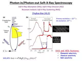
Why Extreme Ultraviolet & Soft X-rays? Thin Film or Multilayer Mirrors EUV Lithography (making really small computer chip features) BYU EUV Optics Soft X-ray Microscopes November 5, 2003 EUV Astronomy The Earth’s magnetosphere in the EUV Images from www.schott.com/magazine/english/info99/ and www.lbl.gov/Science-Articles/Archive/xray-inside-cells.html.
BYU EUV Optics November 5, 2003 EUV & soft x-rays • Visible is ~400 to ~700 nm (1.7 to 3 eV) • UV down to about 170 nm (~7 eV) • VUV- Vacuum UV (starts where N2 is absorbing) then there is FUV & EUV • EUV/soft x-ray • 47 nm is the λ for the Ne-like-Ar X-ray Laser, (Capillary Discharge- CSU, Jorge Rocca ) But • (projection) EUV lithography at ~13.5 (92 eV). • X-rays first understood came from electrons being knocked out of K shell and electron falling in. • I put the division at about 11 nm (110 eV)- Be K edge.
Goal: To maximize delivery of light in the EUV Problem: EUV is absorbed quickly by most materials; a beam of EUV light is absorbed in 100 nm of H2O. Even worse, conventional optical devices will not reflect EUV light. Solution: Use thin films or multiple layers to optimize reflectance Most of the light that passes through the top layer will be reflected from a subsequent layer. H/L stacks If the thicknesses and compositions of all films are carefully controlled the reflected light will constructively interfere resulting in the brightest possible reflection. BYU EUV Optics November 5, 2003 Why Ultrathin Films Reflectors?
Why Projects in the EUV ~ 45 nm? • We have experience (Image Space craft) • Laser. • Consider planned 13.5-nm lithography
Projection EUV lithographic • Big jump from 157 to ~13 nm. Before this has about ¼ increase in energy. Now 10x. • Mo/Si ~40 layer pairs ~68% reflectance Where Mo and Si are most transparent. • Mo/Be is higher but narrower.
Why not a stop at ~46 nm? • Hard to get high reflectances • Materials and thicknesses • A Russian group suggested scandium/ silicon MLs. Scandium was “calculated” to have exceptional transparency above ~ 35 nm. Computed normal incidence R of ~70%. • Highest seen is in the 40%’s- evidence of substantial interdiffusion.(~2 nm/interface)
Scandium • We tried Sc/Al ML • No evidence of layering • We examined binary phase diagrams and literature optical data. • Sc & V
How to use it • Sc as spacer. V as Absorber • Scandium / Si or Al with V as barrier
Intermediate Steps • Optical constants • Optical constants and thicknesses of oxides • Getting clean surfaces
Hydrocarbon Buildups Lower Reflectance Reduced Reflectance with Hydrocarbon Thickness. Theoretical change in reflectance vs. grazing angle and organic thickness. (at λ=40.0 nm)
Four Methods of Cleaning Tested • Opticlean® • Oxygen Plasma • Excimer UV Lamp • Opticlean® + Oxygen Plasma
UV Lamp Theory • High energy photons break up hydrocarbon bonds. Volatile fragments leave the surface. • UV produces oxygen radicals which react with oxygen gas to form ozone. The reactive ozone & UV oxidize contaminants and they evaporate.
Studying Our Samples BYU EUV Optics November 5, 2003 Ellipsometry Scanning/Tunneling Electron Microscopes (SEM/TEM) X-ray Photoelectron Spectroscope (XPS) Atomic Force Microscopy (AFM) Images courtesy of http://www.weizmann.ac.il/surflab/peter/afmworks/,http://www.mos.org/sln/SEM/works/, http://www.swt.edu/~wg06/manuals/Gaertner117/ellipsometerHome.htm and http://volta.byu.edu/adamson03.pdf.
UV Results • 4.5 Å DADMAC layer eliminated rapidly, followed by slow oxidation. • XPS shows no carbon peak. • Concern: silicon doesn’t appear to oxidize, but mirror coatings such as U and Ni do.
BYU EUV Optics BYU EUV Optics October 10, 2003 November 5, 2003 Taking Reflectance Measurements with the Monochromator
40 nm results to date • We have learned how to clean up some substrates and samples • protocols to study oxides • Spend too much time of preparation • Will use facts learned soon to prepare ML
Klaprothium • In late 18th Century German Chemist, Klaproth discovered a new element which some suggested be called after him. • He called it Uranium. I will call it Kp • He died in early decades of 19th Century, thinking he had isolated the element Uranium • About two decades later however • This reaction was use Kp + 2C + 2Cl2→ 2CO + UCl4. • This established kp was actually and oxide • Now known to be UO2
BYU EUV Optics October 25, 2003 Why Uranium? • Uranium has many electrons to interact with photons (light) and is more dense than many materials, causing them to interact with high energy EUV photons. • High Theoretical Reflectivity: Low absorption, β and high δ • Previous Success: IMAGE Satellite Mirror Project (Launched March 25, 2000)
BYU EUV Optics October 25, 2003 Delta vs. beta plot for several elements at 4.48 nm 4.48nm Note: Nickel and its neighboring 3d elements are the nearest to uranium in this area.
BYU EUV Optics November 5, 2003 Taking Reflectance Measurements at the ALS (Advance Light Source) Inage courtesy of http://www.lbl.gov/
Uranium Oxide as a Highly Reflective Coating from 2.7 to 11.6 Nanometers- • specific application low-angle of incidence.
BYU EUV Optics October 25, 2003 Reflectances for Ni, NiO, U, and UO2 predicted by the atomic scattering factor model from the Center for X-Ray Optics (CXRO) website (www-cxro.lbl.gov).
Measured reflectances of UOx, NiO on Ni, and Ni on quartz at 5 degrees from 2.7-11.6 nm
Measured reflectance at 10 degrees of UO2, NiO on Ni, Ni on Quartz from 2.7-11.6 nm
Measured reflectance at 15 degrees of UO2, NiO on Ni, and Ni on Quartz from 2.7-11.6 nm.
BYU EUV Optics October 25, 2003 [i] Sandberg et a., Advances in Mirror Technology for X-Ray, EUV Lithography, Laser, and Other Applications, Ali M. Khounsary, Udo Dinger, Kazuya Ota, Editors, Proc. SPIE 5193, SPIE, Bellingham, WA, 2003. [ii] Shannon Lunt, Determining the Indices of Refraction of Reactively Sputtered Uranium Dioxide Thing Films from 46 to 584 Angstroms, Masters Thesis, Dept. of Physics and Astronomy, BYU, Provo, UT 2002.
BYU EUV Optics October 25, 2003
BYU EUV Optics October 25, 2003 Conclusions- 1 • In an UG student environment, We know how to • Clean Si surfaces • Study oxidation • We are making Sc based mirrors and want collaborations
Conclusions 2 • Uranium oxide reflects significantly better than nickel, the current material with highest reflectance, between 4 and 11 nm. • Uranium oxide reflectance differs from the reflectance predicted by the atomic scattering factor model (ASF). • Reflectances of naturally oxidized uranium (UO2) matches reactively sputtered UO2 –Thus the material (Klaprothium) can be made in a number of different ways and is stable enough for practical use.
BYU EUV Optics October 10, 2003 Measured reflectance of UOx, NiO on Ni, and Ni on quartz at 5˚ Conducted at the ALS From Richard L. Sandberg, David D. Allred, Jed E. Johnson, R. Steven Turley “A Comparison of Uranium Oxide and Nickel as Single-layer Reflectors from 2.7 to 11.6 Nanometers,” in Advances in Mirror Technology for X-Ray, EUV Lithography, Laser, and Other Applications, Ali M. Khounsary, Udo Dinger, Kazuya Ota, Editors, Proc. SPIE 5193, SPIE, Bellingham, WA, 2003.
BYU EUV Optics October 10, 2003 [i] Sandberg et a., Advances in Mirror Technology for X-Ray, EUV Lithography, Laser, and Other Applications, Ali M. Khounsary, Udo Dinger, Kazuya Ota, Editors, Proc. SPIE 5193, SPIE, Bellingham, WA, 2003. [ii] Shannon Lunt, Determining the Indices of Refraction of Reactively Sputtered Uranium Dioxide Thing Films from 46 to 584 Angstroms, Masters Thesis, Dept. of Physics and Astronomy, BYU, Provo, UT 2002.
BYU EUV Optics October 10, 2003 Recent BYU EUV Group Successes • Produce the Neutral Particle Detector mirror for the Mars Express Mission funded by the European Space Agency (Launched on June 2, 2003). • Produced the EUV Mirrors for the IMAGE satellite funded by NASA and the Southwestern Research Institute (Launched on March 25, 2002). • 6 Trips to the Advanced Light Source (ALS) at Lawrence Berkeley National Laboratory • Selected Awards/Scholarships: • Outstanding Manuscript/Presentation in Physics at Utah Academy 2003—Kristi R. Adamson • Best Student Presentations at 2002 APS Four Corners Conference—Kristi R. Adamson, Richard L. Sandberg • 2003 Goldwater Scholarship—Kristi R. Adamson • 2003 BYU ORCA Scholarships—Luke J. Bissell, Ross Robinson • 2003 SPIE Scholarship—Richard L. Sandberg • 2003 John Hale Gardner Scholarship—Richard L. Sandberg • 2002 SPIE Scholarships—Luke J. Bissell, Guillermo A. Acosta • Selected Publications: • David D. Allred, Matthew B. Squires, R. Steven Turley, Webster Cash, and Ann Shipley, “Highly Reflective Uranium Mirrors for Astrophysics Applications,” in X-ray Mirrors, Crystals and Multilayers, Andreas K. Freund, Albert T. Macrander, Tetsuya Ishikawa, and James. T. Wood, Editors, Proc. SPIE 4782, pp. 212-223, SPIE, Bellingham, WA, 2002. • Kristi R. Adamson, R. Steven Turley, David D. Allred, “Determining Composition through X-Ray Photoelectron Spectroscopy,” in Journal of the Utah Academy (Accepted for publishing, official reference forthcoming, originally presented April 11, 2003). • Richard L. Sandberg, David D. Allred, Jed E. Johnson, R. Steven Turley, “A Comparison of Uranium Oxide and Nickel as Single-layer Reflectors from 2.7 to 11.6 Nanometers,” in Advances in Mirror Technology for X-Ray, EUV Lithography, Laser, and Other Applications, Ali M. Khounsary, Udo Dinger, Kazuya Ota, Editors, Proc. SPIE 5193, SPIE, Bellingham, WA, 2003. • Richard L. Sandberg, David D. Allred, Luke J. Bissell, Jed E. Johnson, R. Steven Turley, “Uranium Oxide as a Highly Reflective Coating from 100-400 eV,” in Proceedings of the Eighth International Conference on Synchrotron Radiation Instrumentation, San Francisco, 2003, American Institute of Physics. (To be published, official reference forthcoming).
BYU EUV Optics October 10, 2003 For more information… BYU EUV WebPages: http://xuv.byu.edu/ http://volta.byu.edu/xray.html Or contact Dr. Allred or Dr. Turley: allred@byu.edu, 801-422-3489, Office is N265 ESC turley@physics.byu.edu, 801-422-3095, Office is N308 ESC Group Meetings: 3:00 pm on Tuesdays, C247 in the Eyring Science Center (ESC)
BYU EUV Optics November 5, 2003 Making Thin Films • Films are made using a process called sputtering or through thermal evaporation. These processes are conducted in high vacuum systems. • For sputtering, a target or piece of the material we want deposited as a film, is bombarded with ions from the RF argon plasma causing particles to be released from the target which then deposit to the silicon or quartz substrate. • For thermal evaporation, a wire or boat is resistively heated by passing a large current through it. The heated metal (ie. aluminum, nickel, gold) evaporates and is deposited on the silicon or quartz substrate.
BYU EUV Optics November 5, 2003 Taking Reflectance Measurements • Our Very Own Reflectometer • Monochromator • Mono: one. Chromatic: color. • A grating, like a prism, diffracts the light into a rainbow. • The rainbow falls on a pinhole so that only one wavelength passes through. • Octagonal Chamber • Light enters the chamber and is reflected from the surface being studied. • The reflected light is measured as a function of angle. • The Advanced Light Source • Fieldtrips to the Lawrence Berkeley National Laboratory in Berkeley, CA to use their Advanced Light Source (Synchrotron—accelerated beam of electrons produces bright EUV/X-ray light).
BYU EUV Optics October 10, 2003 Calculating Optical Constants and Reflectance (A quote from the Center for X-ray Optics) The primary interaction of low-energy x rays within matter, viz. photoabsorption and coherent scattering, have been described for photon energies outside the absorption threshold regions by using atomic scattering factors, f1and f2. The atomic photoabsorption cross section, µa, may be readily obtained from the values of using the relation: where r0 is the classical electron radius, and λ is the wavelength. The transmission of x rays through a slab of thickness d is then given by: where n is the number of atoms per unit volume in the slab. The index of refraction for a material is calculated by: These (semi-empirical) atomic scattering factors are based upon photoabsorption measurements of elements in their elemental state. The basic assumption is that condensed matter may be modeled as a collection of non-interacting atoms. This assumption is in general a good one for energies sufficiently far from absorption thresholds. In the threshold regions, the specific chemical state is important and direct experimental measurements must be made.[i],[ii] [i] CXRO webpage (July, 2003). http://www-cxro.lbl.gov/optical_constants/intro.html. [ii] B.L. Henke, E.M. Gullikson, and J.C. Davis, X-ray interactions: photoabsorption, scattering, transmission, and reflection at E=50-30000 eV, Z=1-92, Atomic Data and Nuclear Data Tables 54 no.2, 181-342 (July 1993).
BYU EUV Optics October 10, 2003 Why Uranium and Thorium? • In the EUV, uranium and thorium have many electrons to interact with photons (light) and is more dense than many materials, causing them to interact with high energy EUV photons. • We study different compounds of uranium and thorium, such as uranium-oxide (UO2), uranium-nitride (UN), and thorium-oxide (ThO2) in search of compounds with the best optical constants and that do not react with air.
BYU EUV Optics October 10, 2003 Reflectance computed using the CXRO Website: http://www-cxro.lbl.gov/optical_constants/mirror2.html
BYU EUV Optics October 25, 2003 Acknowledgements Hollilyn Drury and Megan Rowberry (Provo High School) aided in sputtering the uranium films studied. An SPIE scholarship and department funding aided Richard Sandberg in the research. We also acknowledge gratefully the financial contributions of V. Dean and Alice J. Allred and Marathon Oil Company (US Steel) and Nan Ellen Ah You for gifts to Brigham Young University for thin film research. We would also like to thank the ALS for the beamtime used to make the optical measurements.