Download
1 / 18
180 likes | 309 Vues
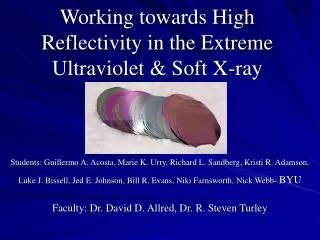
Determining Ruthenium’s Optical Constants in the Extreme Ultraviolet . Luke J. Bissell, David D. Allred, R. Steven Turley, William R. Evans, Jed E. Johnson. Multilayer mirrors for EUV lithography. Goal is to get a mirror that has maximum reflectance in the range of 11-14 nm

E N D
Determining Ruthenium’s Optical Constants in the Extreme Ultraviolet Luke J. Bissell, David D. Allred, R. Steven Turley, William R. Evans, Jed E. Johnson
Multilayer mirrors for EUV lithography • Goal is to get a mirror that has maximum • reflectance in the range of 11-14 nm • Multilayers maximize the constructive • interference of thin films by repetition of • high index/low index materials • Molybdenum/silicon multilayers have been • made which reflect 70% at 13.5 nm at 5° • from normal incidence [2] [1]
Why ruthenium? • Ru is the closest neighbour to Mo that has a similar absorption coefficient (f2) and doesn’t oxidize • Ru f2 of 2.89 at 13.5 nm, compared to 1.23 for Mo at the same wavelength [2]. • Ru capped multilayers have better long-term reflectance than older design [3]. • Long Term Goal: study the reflectance of a Mo/Si multilayer capped with a Ru-Mo alloy.
Short term goal: getting d & b • The absorption coefficient (b) can be extracted from *transmission data • We can use Fresnel’s equations to fit the complex index of refraction to reflectance data • Interested in wavelengths between 11 and 14 nm. • Used Ru thin films *where T is the transmission after correction is made for reflection
Experimental details • Three films were prepared during two depositions via RF magnetron sputtering at a base pressure < 8 E -7 torr. • Films were deposited on: • polished Si (100) substrates • transparent polyimide window from Moxtek, Inc. • Reflectance and transmission measurements were made at the Advanced Light Source at LBNL
Characterization • To fit d and b to reflectance data, we need an accurate model of our sample: • SiO2 thickness determined by ellipsometry prior to • deposition • Ru thickness determined by fitting x-ray reflectance at • 0.154 nm and at 11-14 nm • Our previous research indicates • Ru oxide thickness is negligible Ru thin film (not to scale) Ru Si02 Si substrate
a b Reflectance Reflectance Reflectance Reflectance l l l l = 13 nm = 13 nm = 11.5 nm = 11.5 nm theta theta theta theta Reflectance vs. Incidence Angle • Fitting done with JFIT 1st deposition 2nd deposition
coated uncoated Lambert’s law • used T = TRu=Tcoated/Tuncoated • d = 21.32 nm • assumed (1) both polyimide films were the same thickness (2) same thickness for samples B and C • R = ¼(d2 + b2)
sample B sample A Issues relative to fitting reflectance data
(■) this study, weighted average (Δ) Windt et al. (●) the ASF values (Henke et al.) (▲) Windt (unpublished)
(■) this study, weighted average (Δ) Windt et al. (●) the ASF (Henke et al.) (▲) Windt (unpublished)
Summary • We have measured the complex index of refraction for Ru from 11-14 nm. • Comparison with other sources shows differences as great as 20% between our measured d and b values and those reported by other authors • We will deposit a Mo-Ru alloy and study its stability
SPIE BYU V. Dean and Alice J. Allred Marathon Oil Acknowledgments Work suported by: Special thanks to Eric Gullikson and Andy Aquila at ALS Beamline 6.3.2 for their help in data interpretation, reduction, and analysis.
References [1] Atwood, David. Soft X-Rays and Extreme Ultraviolet Radiation. Cambridge 1999. p. 113 [2] “X-ray Properties of the Elements,” http://www-cxro.lbl.gov/optical_constants [3] S. Bajt, J.B. Alameda, T.W. Barbee Jr., W.M. Clift, J.A. Folta, B. Kaufmann, E.A. Spiller, “Improved Reflectance and Stability of Mo-Si multilayers,” Opt. Eng.41, 1797-1804 (2002). [4] D. L. Windt, W. C. Cash, M. Scott, P. Arendt, B. Newman, R. F. Fisher, A. B. Swartzlander, “Optical constants for thin films of Ti, Zr, Nb, Mo, Ru, Rh, Pd, Ag, Hf, Ta, W, Re, Ir, Os, Pt, and Au from 24 Å to 1216 Å,” 27 (2), 246-278 (1988). [5] B.L. Henke, E.M. Gullikson, J.C. Davis. “X-ray interactions: photoabsorption, scattering, transmission, and reflection at E=50-30000 eV, Z=1-92,” Atomic Data and Nuclear Data Tables, 54 (2), 181-342 (1993).