Download
1 / 27
270 likes | 448 Vues
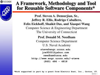
A Framework for Designing Reusable Analog Circuits. Dean Liu, Stefanos Sidiropoulos, Mark Horowitz Computer Systems Laboratory Stanford University. Digital CAD Tools. Digital design leverages highly on automation Binary logic abstraction Similar constraints and goals for each circuit.

E N D
A Framework for Designing Reusable Analog Circuits Dean Liu, Stefanos Sidiropoulos, Mark Horowitz Computer Systems Laboratory Stanford University
Digital CAD Tools • Digital design leverages highly on automation • Binary logic abstraction • Similar constraints and goals for each circuit Logic Verification Timing Verification DRC LVS ERC Gate-Level Synthesis FU-Level Synthesis Schematic HDL Time D. Liu, S. Sidiropoulos, M. Horowitz
Analog CAD Tools • Analog circuits are mostly custom designed • Wide range of functionalities • Implicit goals and constraints • Different checks and objective for each circuit DRC LVS Multi-Variable Optimization SPICE Schematic Time D. Liu, S. Sidiropoulos, M. Horowitz
Documentation • Want documentation to record designer’s intention • Circuit topology and sizes records answers not problems • Ask analog designers to comment their circuits • Computer programmers comment their code, right? • Offer incentives to encourage documentation • Make the documentation benefit the current designer D. Liu, S. Sidiropoulos, M. Horowitz
Application sets specifications and foundries impose manufacturing constraints Design process cycles between synthesis and verification Synthesis Verification Review of the Design Process D. Liu, S. Sidiropoulos, M. Horowitz
Make assumptions and local sub-goals For example: transistor saturation Select circuit topology For example: op-amp (single-stage, multi-stage, …, etc.) Formulate analytical equations to guide design decisions For example: bandwidth, gain Size devices Satisfy performance envelope Design Process: Synthesis D. Liu, S. Sidiropoulos, M. Horowitz
Simulate circuits (typically SPICE or derivatives) Validate design across multiple operating environments Measure circuit parameters Evaluate analytical equations based on simulated values Verify assumptions For example: check transistors are operating correctly Goal: explore limitations of the circuit Figure out where and how the circuit breaks Design Process: Verification D. Liu, S. Sidiropoulos, M. Horowitz
Circuit Representation Circuit Netlist (.spi) Results Circuit Simulator Stimuli (.hsp) Pre-Processing Post-Processing Design: Circuit Simulation D. Liu, S. Sidiropoulos, M. Horowitz
STAR • Schematic is the archival representation for analog circuits • Annotate specifications and goals on the schematic • Need mechanism to specify the constraints • Turn annotations into simulation and data collection routines • Schematic Tool for Analog Reuse (STAR) D. Liu, S. Sidiropoulos, M. Horowitz
Schematic Window Vctrl Active Comment Predefined Functions Library Execution Engine STAR: Active Comment Operation • Written on circuit’s schematic • Composed of predefined functions • Executed by a prototype engine D. Liu, S. Sidiropoulos, M. Horowitz
Ref CP PFD vvdd ck L2H Div_N en STAR: PLL Example • Composed of mixed-signal and analog blocks • Modeled as linear second order system D. Liu, S. Sidiropoulos, M. Horowitz
Vctrl ck L2H STAR: Production Schematic vs. Test Bench • Production schematic: schematic with layout • Test bench: schematic used for test and characterization • Create scaffolding to configure, drive, and/or load circuit CP PFD Div_N L2H D. Liu, S. Sidiropoulos, M. Horowitz
Freq Vctrl ck L2H Vctrl STAR: Measurement Example • Want to model PLL as linear system • Limit VCO operation to linear region • Use the Vctrl range in other comments D. Liu, S. Sidiropoulos, M. Horowitz
Vctrl ck L2H STAR: Measurement Detail Freq Fast corner Slow corner Vctrl vLo vHi Sweep control voltage from 0 to Vdd at fast corner, find lower inflection point, assign it to vLo Sweep control voltage from 0 to Vdd at slow corner, find upper inflection point, assign it to vHi Variable=Post-processor;Pre-processor;Simulation corners # DEFINE vLo=LoRange(vctrl,Freq(ck)) w/ SweepV(vctrl,gnd,vdd) @ ffhl # DEFINE vHi=HiRange(vctrl,Freq(ck)) w/ SweepV(vctrl,gnd,vdd) @ sslh D. Liu, S. Sidiropoulos, M. Horowitz
* checker simulation deck .prot .lib 'mosis.lib' ff .unprot .temp 0 .param vddval='1.1*3.3' .param vlow=0 vdd vdd gnd dc vddval .inc 'vcoV2.spi‘ .inc 'vcoV2.inc‘ .param swp_vint=0 Vswp_vint vint gnd dc swp_vint .tran 32p 160n uic +sweep swp_vint 0 3.3 '(3.3-0)/20' * generate a vdd/2 reference efreq vfreq_ck gnd vdd gnd 0.5 .meas tran per + trig v(ck,vfreq_ck) val=0 rise=5 + targ v(ck,vfreq_ck) val=0 rise=6 .meas tran freq_ck param='1/per' .end STAR: Generated Simulation Deck D. Liu, S. Sidiropoulos, M. Horowitz
STAR: Performance Checks • Apply Measurements only to “top-level” circuit • Measurements in lower levels not executed • Keep circuit performance satisfied • Constantly monitor and check circuit • Guarantee performance regardless of stimuli • Check all instances of circuit • Must propagate the performance checks up hierarchy • Create another type of active comment: Assertion • Analogous to assertions in computer programs D. Liu, S. Sidiropoulos, M. Horowitz
upi cs cs Vout Ibias cs dni STAR: Assertion Example • Check transistor saturation for current sources • Verify transistor saturation margin in all simulations • Mark current source transistors D. Liu, S. Sidiropoulos, M. Horowitz
upi cs cs Vout Ibias cs dni STAR: Assertion Detail For transistors marked with the cs label, check saturation margin to be at least 5% of supply Post-processorConstraint # ASSERT SatMargin(cs) >= 0.05*vdd D. Liu, S. Sidiropoulos, M. Horowitz
Vctrl Active Comment Schematic Capture Predefined Functions Library Parser Execution Engine Libraries Primitives Prototype Implementation • Predefined functions may change with class of circuits • Keep prototype flexible to allow the user to extend it D. Liu, S. Sidiropoulos, M. Horowitz
Prototype: Annotated Schematic D. Liu, S. Sidiropoulos, M. Horowitz
Prototype: Comments View • Need annotation • Comments View • Instantiateinto the schematic • Comments in the schematic are instances and are not editable • Grow as circuit evolves • Annotation is a live document D. Liu, S. Sidiropoulos, M. Horowitz
Prototype: Auto Help Function D. Liu, S. Sidiropoulos, M. Horowitz
Prototype: Library • New circuits may require new functions • Provide a flexible and extensible programming environment • Circuit designers are not programmers • Need to reduce programming effort and hide complexity • Perl seems just right for the job • User extensions must be archived with schematic D. Liu, S. Sidiropoulos, M. Horowitz
Prototype: Primitive • Some tasks are computation intensive • Reading waveforms and extracting timing information • Re-code routines in C for better performance • Increased programming effort and complexity D. Liu, S. Sidiropoulos, M. Horowitz
Schematic Window Comments Editor Re-optimization by circuit designer File Edit Vctrl Finding the low range # DEFINE vLo=… Transient Measure Post-sim Directives Inc File (.inc) Post-sim Directives Results # DEFINE vLo_c= LoRange(vctrl,Freq(ck)) \ w/ SweepV(vctrl,vLo,vHi) @ ffhn Simulator (HSpice) Verifier Spice Decks (.hsp) Spice Deck (from user) Prototype: Proposed Design Flow D. Liu, S. Sidiropoulos, M. Horowitz
Conclusion • Encapsulate design knowledge • Embed designer’s intent and experience in schematic • Capture circuit functionality and performance goals • Ensure correct circuit behavior at all levels • Provide two programming interfaces • Allow trade-off between coding effort and performance D. Liu, S. Sidiropoulos, M. Horowitz
Acknowledgement • C2S2 Marco Center for support of this research D. Liu, S. Sidiropoulos, M. Horowitz