Download
1 / 27
270 likes | 554 Vues
FERMI@ELETTRA REPORT. Simone Spampinati. on behalf of the FERMI team. Outlook. FERMI Presentation and design. FERMI@ELETTRA Linac design. FERMI commisioning. Commisioning of laser heater, and x-band Phase space control Emittance preservation

E N D
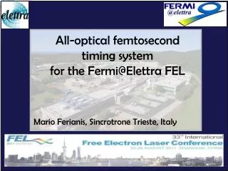
FERMI@ELETTRA REPORT Simone Spampinati on behalf of the FERMI team
Outlook • FERMI Presentation and design • FERMI@ELETTRA • Linac design • FERMI commisioning • Commisioning of laser heater, and x-band • Phase space control • Emittance preservation • FEL1 performance in the nominal wavelength range • FEL2 starting commissioning • FEL1 as test facility in the soft x-ray • Conclusion • Double stage cascade • Harmonic cascade
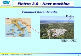
FERMI at the ELETTRA LABORATORY SINCROTRONE TRIESTE is a nonprofit shareholder company of national interest, established in 1987 to construct and manage synchrotron light sources as international facilities. ELETTRA Synchrotron Light Source: up to 2.4 GeV, top-up mode, ~800 proposals from 40 countries every year • FERMI@Elettra FEL: • 100 – 4 nm HGHG, fully funded • Sponsors: • Italian Minister of University and Research (MIUR) • Regione Auton. Friuli Venezia Giulia • European Investment Bank (EIB) • European Research Council (ERC) • European Commission (EC) 200 m Linac Tunnel + Injector Extension 100 m Undulator Hall 50 m Experim. Hall
FERMI main features Two separate FEL amplifiers to cover the spectral range from 100 nm (12eV) to 4 nm (320 eV) Radiation feature Electron beam parameter and requirement • high peak power (0.3 – GW’s range) • short temporal structure (150-10 fs) • Good transverse and longitudinal coherhence • tunable wavelength • variable polarization (horizontal/circular/vertical) • Charge 500-800 pC • Current 500-800A • Slice Emittance <1.5 mm mrad • Energy 1.2-1.5 GeV Restricted list from the scientific case • High resolution spectroscopy of low density matter • Pump probe spectroscopy • Coherent diffraction imaging
FERMI Layout experimental hall Photon Beam Lines PADReS EIS slits FEL1 DIPROI FEL2 LDM I/O mirrors & gas cells 5
FEL 1 AND FEL 2 FEL 1 FEL 2 • FEL-1: seeded FEL single stage high gain harmonic generation (HGHG) • UV seed laser: 3° of Ti:Sa or OPA • Energy modulation on the wavelength scale of the seed laser • Output wavelength from 100 nm down to 20nm. • FEL-2: Double stage of HGHG • Fresh bunch technique implemented with a magnetic delay line • UV seed laser: 3° Ti:Sa or OPA • Output wavelength from 20 nm down to 4nm. 6
Design and working point of FERMI@ELETTRA linac (1) • Good region of the electron beam has to be long enough to accommodate seed-electrons time jitter • and slippage. 100 fs jitter and 150 fs seed: 300-400 fs good region of electron beam for FEL1, 500 fs for FEL2 • Peak current I>500 A (800 nominal) to provide good photon flux and contained gain length : • C=I×∆T: C>500 pC (800 pC) • Compression factor CF ~10. Mild compression factor • Higher harmonic reached by HGHG is limited by energy spread • 120-150keV energy spread is required • One compressor scheme and laser heater help to contain microbunching and reduce energy spread • Final energy spread vs starting one Courtesy of M.Venturini Vlasov solver calculations
Design and working point of FERMI@ELETTRA linac (2) • HGHG is sensible to nonlinearity in electron beam phase space • E-beam linear energy Chirp + Dispersive Section produces a shift in FEL output fequency and • then a frequency jitter • E-beam quadratic Chirp + Dispersive Section produces a bandwidth increase dispersive e- e- quadratic Chirp Chirp and modulation Bunching and compression • Residual chirp from compression can be compensated with L4 phase • Strong weak in the old ELETTRA linac structure introduce strong quadratic chirp • X can be optimized to compensate quadratic chirp or to linearize current • Start from a particular electron beam current distribution at photocathode (to do)
Tools to control longitudinal phase space From May Laser Heater • Control of linac microbunhing • Short scale length homogeneity • Reduction of COTR and CSR • Control of slice energy spread X-band From May • Linearization of compression • Flat top current profile • Longer green region (slide 7) • Highr compression possible From February • High energy deflector • Phase space imaging @Llinac • end
Laser Heater • Laser heater system in the linac tunnel • input laser table • chicane magnet • multiscreen station LH01.02 (CROMOX) • laser heater undulator • multiscreen station LH01.03 • bpm LH01.03 (CROMOX) • output laser table. Heater off Heater on • Beam heated deflected and sent in a spectrometer • with ~0.58m dispersion • Spectrometer located after BC1 @320 MeV • Chicane and all cavity on creast (X-BAND in off) • Slice energy spread measured without heater 40 KeV ( optic +deflector) • Maximum energy spread with heater on is 100KeV (160µJ laser energy). • Laser spot size 200µm electron beam 140µm
Energy spread versus laser energy • Energy spread for no heating is removed in quadrature from data • Red points are data of the energy spread added by the heater • Green error bar from statistic errors • Blue line for theoretical behavior • Magenta points (on the bottom) Theory (only laser modulation without LSC)-Measurements Laser Spot 200 µm 160µJ
Heating measurement • Energy spread added by heater versus undulator gap • Energy spread for no heating is removed in quadrature from data • Green points are data of the energy spread added by the heater • Best gap 27.67mm. Predicted 27.3mm →97.2MeV instead of 97.7MeV • Slice energy spread added by the heater • along the bunch • Green curve: Energy spread with heater • in off • Red curve: Measured with heater on (160µJ) • Blue curve energy spread added Beam profile (ps)
500 pC, no X-band cavity, CF=5.6 • Residual chirp from compression • Beam energy spectrum measured in DBD • for several setting of laser heater • Reduction and suppression of beam modulation Microbunching suppression • Suppression of COTR after spreader • (screen sfel01.02) • 350 pC, X-BAND,CF=10 • >1µJ laser energy to suppress COTR (>10KeV). • ~1% of further reduction inserting an OTR • before this one 20µJ Laser 20µJ Laser+sfel01.01
X-band • 4° harmonic cavity of S band installed in L1 • to linearize the energy chirp with L1 off crest • linearize compression • Nominal working point on decelerating crest (-20MeV):near flat current Linearize phase space Linearize compression to obtain flat current
High energy deflector for phase space and current profile H deflector V deflector Not installed • Horizontal deflecting cavity installed in the linac to spreader transfer line • High dispersion spectrometer: ~1.8m • spectrometer energy spread resolution by twiss function, dispersion and screen resolution 60keV • Optical functions have same variation along the bunch than resolution too. Energy spread from deflector • Longitudinal resolution >30fs 500 pC CF=1 X-band off Courtesy of G.Penco
Longitudinal Phase space without laser heater and x band • 500 pc CF=5.6 • L4 @+30deg • Ramped current distribution • Linear chirp • Microbunching Courtesy of G.Penco
Longitudinal Phase space with laser heater and x-band • 500pc CF~10-12 • X-band@270deg -20MeV • L4@+30deg to compensate linear chirp • Linear chirp<1MeV/ps • Quadratic term 1MeV/ps² • Small energy variation along the bunch • Is it possible compensate the quadratic term • with X-band@265deg • Flat current • Small core energy spread • Is it possible reduce energy spread with X-band@265deg (residual slope on the current and lower current and lower photon flux) Courtesy of G.Penco
FEL1 performances • Data taken in a user shift Timex • CF~10-12 • C=500pC • X-band@270 deg -20MeV • L4@+30 deg to compensate linear chirp • 248nm/7 FEL stability and performance over 400 shots Wavelength= 35.4 nm Photon energy= 35.0 eV Lambda jitter = 0.016 nm 0.046 (%) Bandwidth(rms) = 0.022 (nm) 22.0 meV 6.2e-04 Bandwidth jitter = 0.0065 (nm) 29 (%) Pulse energy= 200µJ Courtesy of E. Allaria
Laser heater effect on FEL1 • 100 spectra taken with the laser heater switched, figure on the top • 100 spectra taken with the laser heater off, figure on the bottom • 500 pc CF=10 in BC1. X-band on. Laser transverse dimensions 140µm • Black lines are the main spectrum. • Laser heater clean the spectrum Gaussian like Noisy and spiky
Laser heater effect on FEL1 • FEL intensity on ionization gas monitor vs seed laser energy for different laser heater settings • Circular polarization • Data of 13 July 2012 LDM shift • 500 pc CF=10 in BC1. X-band on. Laser transverse dimensions 140µm
Higher harmonic test • FEL1 nominal range of operation is down to 20nm 13° harmonic of the seed • The electron beam was so good in July to reach a pulse energy of 200 µJ at 20 nm • Tests with higher harmonic • Whit this beam 28° seems to be the limit of the single stage
FEL2 commisioning • Tested first stage of FEL2 • Used the only diagnostics available • Synchronization between seed laser and electron found by looking on the electron beam dump. • Footprint of laser energy modulation • Emission on first radiator observed • Verified laser transport and initial synchronization • calibration of three undulator (of 10) • At least 1µJ has been obtained from the two • radiator of the first stage (tens of nJ were obtained • from 6 radiators in the first light of FEL1) Space for 2 sections Installed now Observed here Done here
Double cascade test with FEL 1 • We tune the last two radiator undulator on a harmonic of the first four • The bunching is propagated from one stage to the other • In this configuration every stage is resonant on one harmonic of the previous stage • Coherent emission on the fundamental • Coherent emission on the fundamental • Too high energy modulation is requested • to have bunching. • Longer gain length in the second undulator. • only coherent radiation in the radiator • Less energy modulation by seed • Shorter gain length in the second • undulator • Coherent emission on the fundamental • FEL gain and exponential growth • Strong harmonic bunching near sat • Bunching could be enhanced by slippage • Better bunching in the last stage • Configuration with 3/3 and 5/1 worst • Coherent emission on fundamental x7
Double cascade test with FEL 1 • Double stage can go higher in harmonic up conversion • In this case we don’t know the limit: we where limited by undulator calibration available h39
Double stage harmonic cascade test with FEL 1 • Keep going with harmonic up-conversion • We try with an harmonic cascade as second stage • One of the harmonic of the last stage is in resonance with one of the harmonic of beam current • in the previous stage • Coherent emission on the second harmonic • Coherent emission on the • fundamental h1 h2 off axis 4nm h65
Conclusions • Some activities of the last three months of FERMI commissioning have been presented • Laser heater and x-band have been commissioned • Electron phase space closer to nominal one • FERMI1 near specs in the nominal wavelength range • FEL2’ s first stage has been tested • FERMI electron beam is bright enough to reach the water window • Harmonic cascade done for the first time • water window reached • Other activity have been performed in the meanwhile • Improved matching in the undulator region • Improved alignment in the spreader (BBA of quads) • Studies on the trajectory in linac are ongoing • Commissioning of FEL diagnostic and FEL beam line • Works on other system (BPM, current monitor, EOS… ) • Other FEL studies