Download
1 / 15
150 likes | 295 Vues
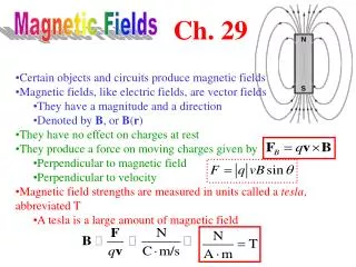
Magnetic Fields. Electric Motors. A direct current (D.C.) motor converts electrical energy (using the current through a coil of wire) into mechanical energy (by spinning the coil.). Force on the current carrying wire . Creates its own magnetic field . Current in a wire .

E N D
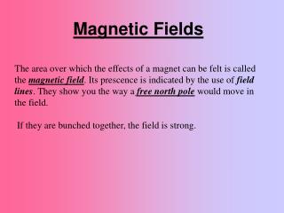
Magnetic Fields Electric Motors
A direct current (D.C.) motor converts electrical energy (using the current through a coil of wire) into mechanical energy (by spinning the coil.) Force on the current carrying wire Creates its own magnetic field Current in a wire Interacts with another field Rotational motion
Note: The current through the far side of the coil is always parallel to the field direction, so there is no force acting on this side.
To get this motor to spin continuously, we need to change the direction of the forces every half cycle. • We could do this by either • reversing the direction of the current (this is the easier option – why?) • or • reversing the direction of the magnetic field • but • not both
To achieve this we use a split-ring commutator The commutator ensures that whichever side of the coil is nearest the north pole will always be pushed up, and whichever side of the coil is nearest the south pole is always pushed down. There are two splits in the ring. (They are seen top and bottom.) These cut the current to the coil twice every complete cycle. There are two carbon brushes on either side of the ring. When in contact with the ring, they complete the circuit and allow current to flow through the coil
When the coil is vertical, the split in the commutator is lined up with the brushes, and no current is flowing through the coil. There is no force acting on the coil, but it continues to rotate clockwise, due to its momentum. The D edge of the coil now makes contact with the left (–) brush, so that current flows from A to D. This means that there is an upward force on the CD side. This causes a continued rotation in the clockwise direction. The coil is horizontal. The D edge of the coil is connected to the right (+) brush at this point, and so current flows from D to A. This results in a clockwise rotation.
http://www.youtube.com/watch?v=N8LUOTQKXlk Electric motor http://www.youtube.com/watch?v=d_aTC0iKO68 2 mins in, an excellent motor explanation http://www.youtube.com/watch?v=Xi7o8cMPI0E another one http://www.youtube.com/watch?v=OpL0joqJmqY an old fashioned one
The turning force F is constant in size (F = BIL) at all points in the cycle. The turning moment or torque () of a force F acting at a distance r from the axis of rotation of a rigid body is defined as = F r In both positions, the size of the force is equal. However, as the coil rotates closer to a vertical position, the line of action of the force moves closer to the axis of rotation (reducing r) Hence, the torque decreases
Torque The unit for is Nm = Fr and F = n BIL Hence = n B I L r
The essential features of a small, DC electric motor are shown in the diagram below. The rotating coil of the motor is connected to a DC supply whose polarity is marked on the diagram. The direction of the magnetic field is also shown on the diagram.
A student built a model DC motor. The motor is shown below. The arrows show the direction of the magnetic field. The coil of the motor was formed from 50 tums of wire. Each turn was rectangular, having length 0.050m (sides WX and YZ) and width 0.030m (sides XY and WZ). The magnetic field can be assumed to be uniform and have a value of 0.048 T. • The student mounted the coil to allow it to rotate freely and placed it between the poles of the magnet. When the terminals of the coil were connected to a battery the coil began to rotate.
A nice little demo. http://video.google.com/videoplay?docid=-6337014556898939402#