Download
1 / 44
440 likes | 449 Vues
Trip Report from SNO and LRT2004. L. Bartoszek BARTOSZEK ENGINEERING 1/5/05. What’s to be covered here:. Things I learned at LRT2004 about reducing background from radioactive contaminants Things I learned about the construction of SNO, particularly the acrylic sphere

E N D
Trip Report from SNO and LRT2004 L. Bartoszek BARTOSZEK ENGINEERING 1/5/05
What’s to be covered here: • Things I learned at LRT2004 about reducing background from radioactive contaminants • Things I learned about the construction of SNO, particularly the acrylic sphere • Many thanks to Art McDonald and others from SNO
Low Radiation Techniques 2004 • http://lrt2004.snolab.ca/ • The conference brought together experts in low background radioactivity assay and purification of detector components and materials, and the development of high purity noble gases. • The world-wide effort in this is much larger than I knew about.
Some topics discussed: • Survey of existing and planned low background facilities and resources. • European facilities • Japanese facilities • North American facilities • Low background detectors, shielding techniques and radiopurity requirements. • New scintillators (optical properties, loading, and purification). • Min Fang gave a talk about Gd-loaded LS • Radon emanation and diffusion studies. • Radon assay techniques.
Topics cont’d • Radon free air, very low background noble gases (free of Rn, Ar and Kr). • Radium assay techniques. • Wash-off, leaching, surface contamination, screening and cleanliness studies. • Water and scintillator purification studies. • Low-level gamma-ray spectrometry. • Neutron activation analysis techniques.
Topics cont’d • ICPMS, atomic absorption and x-ray fluorescence spectroscopy. • Studies of cosmogenic activation of materials. • Software, simulations, electronics, vetoes and in-situ assay techniques. • Simulation of background radiation and cosmic ray backgrounds and neutron fluxes. • Adaptation of industrial processes and instrumentation.
Facilites Represented: • LNGS—Laboratori Nazionali delGran Sasso, Italy (Gran Sasso) • IUS—Boulby Mine Laboratory, UK • LSM—Laboratoire Souterrain de Modane, France (Frejus) • LSC –Laboratorio Subterraneo de Canfranc, Spain (Canfranc) • ILIAS—Integrated Large Infrastructures for Astroparticle Science
More Facilities: • CUPP - Centre for Underground Physics in Pyhäsalmi, Finland • SUL - Solotvina Underground Laboratory, Ukraine • SNOLAB, Canada • Kamioka Observatory, Japan • Ogoya Underground Laboratory, Japan
Still More facilities • Oto Cosmo Observatory, Japan • Kashiwa U.G. Laboratory, Japan • Yang Yang Underground Laboratory, Korea • DUSEL—Deep Underground Science Engineering Lab, US • Many small facilities were also mentioned
Next Picture Stolen from: Radioactive Background Evaluation by Atom Counting C. Orzel Union College Dept. of Physics and Astronomy D. N. McKinsey Yale University Dept. of Physics
Coolest Picture of the conference: Add spatially varying magnetic fields: confine atoms Magneto-Optical Trap (MOT) Collect up to 109 atoms, T ~ 100 mK Trapping due to light forces Constantly scattering photons (Na MOT at NIST)
If you need low background… • Every material that goes into the detector must be screened for radioactive contaminants • U and Th are everywhere because of the atomic testing in the atmosphere • The lower the background desired, the cleaner the material must be and the longer it takes to screen the material • There is significant cost in time and money here
Art’s Vision • Unify the underground laboratory community to share data world-wide • Create databases of pre-qualified vendors of low radiation materials • Organize the collective future efforts similar to the way HEP is organized and plan for new facilities
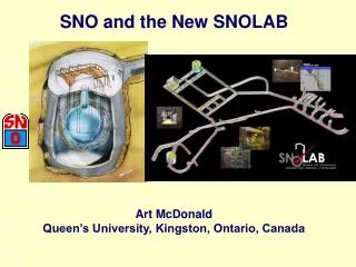
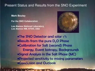
Things I learned about SNO: • SNO deserves every engineering award offered—it is a true engineering marvel • It is the largest cavity at its depth in the world—10 stories tall • It is the cleanest underground laboratory in the world • It has the largest acrylic sphere built to date—12 meter diameter • SNO pioneered large-scale acrylic fabrication techniques
SNO cont’d: • Radon is minimized by covering the entire cavity with nine layers of Urylon HH453 and 201-25 polyurethane paint • The paint was applied in alternating layers of white and gray to see pinhole openings from layer to layer • The goal was to have fewer than 12 radon atoms per m2 per hour diffusing into the water, which required a coating thickness of 8 mm • The thickness was measured by a custom probe using back-scattered X-rays
SNO cont’d • The entire construction was pre-planned to allow for cleanliness. Everything was cleaned and purified—even people • SNO has more plumbing than I’ve ever seen anywhere • See the following pictures:
The RO system for purifying the D2O The RO is just better than break-even in removing impurities. Too much surface area to do much better. I’m not sure if this picture does justice to the density of plumbing I saw, it was everywhere. I have lots more plumbing pictures.
Getting to SNO • First you become a miner. Minimize clothing underneath because it is hot at depth, 6800 feet below the surface of earth. Rock temperature is 41°C. You walk ~1mile horizontally from bottom of elevator shaft • Steps to get to this point • Wash boots • Take off all clothes • Water shower • Don clean clothes, shoes • Air shower
Building the Acrylic Sphere • SNO’s acrylic plate was cast by Polycast, then thermo-slumped into female molds by Reynolds Polymer Technology to produce the spherical sections • After slumping, the sheets were machined to shape on a 5 axis milling machine • Only pure water was used as a cutting fluid • AV was pre-assembled above ground to check fits
Dry fit of panels prior to shipping to the mine—photo courtesy of SNO
Bonding the acrylic • The secret to the success of the construction of SNO was: • A specially formulated polymerizable cement made by Renolds: LUC6751-RT • Room temperature curing • Pot life of ~8 hours to allow pouring of very long joints • Development of repair techniques for imperfectly bonded joints • Much of following comes from the “Handbook of Acrylics” by Jerry Stachiw (who worked on SNO)—very useful book (thanks, Art)
Surface Preparation of panels to be joined • Edges of acrylic parts wetted by cement must be planed or routed smooth • Next is wet sanding with 60 and 120 grit paper on block sander, followed by 240 and 300 on orbital sander • Surfaces adjacent to to the bond gap are wet sanded with 60 and 120 grit paper on block sander • After sanding, parts must be annealed at no less than 185°F for time determined by thickness
Surface Preparation 2 • Wash surfaces of the joint with a water based detergent solution (4% Alconox detergent) • Rinse the surfaces with distilled water • Wipe rinsed surfaces with 20% isopropyl alcohol and dry with paper towels (Santara #2500) • Mask bond gap with masking tape (3M #2090 or equivalent)
Preparation of dams • The cement shrinks by 20% at curing, so the dams must allow a reservoir of cement, and a means of adding more. • The dams are silicon rubber (see next figure) and are cleaned same as acrylic, except no alcohol is used. • Aluminum tape is placed on dams where they will be wetted by cement (3M 591)
Picture from “Handbook of Acrylics” by Stachiw These pictures make it clear that we must have access to both sides of the joint, even for the last joint. The chimney must be designed to accommodate passage of a person.
Scale drawing of a man inside a Braidwood acrylic sphere The chimney as shown is not large enough. Size shows need for internal scaffolding.
Surface prep 3 • The acrylic and the dams must be primed with adhesive primer to ensure the dams do not fall off from the hydrostatic pressure of the cement. • The aluminum tape on the dams is covered with masking tape • Dow Corning 1200 primer is applied to all the surfaces where the dams are glued to the acrylic • Allow to dry for 60 minutes
Bond Preparation • Coat the primed areas of the acrylic and the dams with Dow Corning 790 building adhesive • Allow to cure to tacky to the touch for 30 minutes • Remove the masking tape from the acrylic bond gap surfaces • Do not let any 790 get onto the bonded surfaces because it will prevent polymerization
Bond Prep cont’d • The acrylic panels are put into position using steel scaffolding and turnbuckle jacks to create the desired bond gap of .180 inches • .120” < Bond gap < .250” (more later) • Significant cost of fixturing • Once the glue is tacky, center the dams over the acrylic plates and press them down • Use roller to drive out bubbles, cure for 12 hours
Preparation of the cement • Cement held at 65-75°F for 72 hours • Mix the components of the cement • De-gas the mixture in vacuum bell jars • Pour the cement into the bond gap without entrapment of air • Provide opportunity for entrapped air bubbles to rise to the surface of the bond before it turns viscous • A stainless steel needle can be used to puncture large bubbles
Curing and final surface prep • After 24 hour cure remove the dams • Route off the excess cement • Perform visual inspection of the joint • Sand surfaces in steps up to 600 grit • Post-cure the joint at 175°F for 12 hours • Do not post cure any joint shown by visual inspection to have voids or flaws • If all went well, the joint should be practically invisible
QA checks • Joints are visually inspected, and checked with crossed polarizers and circularly polarized light • Counting fringes quantifies the residual stress in the joint • Working stress on joints must be kept below 1000 psi, and bonded joint tensile strength should be above 9000 psi • Repaired joints rarely get above 6000 psi
Why things are the way they are • The bond gap must not be larger than .250” • The cement cures in an exothermic process • If the gap is larger, the heat runs away and boils the syrup causing voids and residual stress • The cement and acrylic must be held in a narrow temperature range before bonding • Not doing so results in a weaker cold joint, or a weaker boiled joint
More reasons for things • Bond gap must be not be less than .120” • Small gaps prevent adequate flow of cement which leads to voids and cracks • Strength of joints with smaller bond gaps is less than for optimal bond gaps • Rigid spacers must not be used to create bond gap • Residual stress goes way up during curing • SNO used adjustable turnbuckles and manually shrunk the gap during curing
One way to go wrong • If the joint is overfilled, the flexure strength of the joint is reduced by 50% • Routing and sanding brings it back up to parent material strength • Underfilling of the joint reduces the flexural strength by 70% • Routing and finishing makes it worse • That’s why the dams make sure the joint is overfilled
When it’s wrong, cut it out • 5 meters of the 1 km of joints in SNO had to be cut out and repaired • That 5 meters took as long to fix as all the rest of the joints took to make • Repair is a big deal with an elaborate, must be done properly, process (or you do it again. And again.) • Sometimes custom plugs of acrylic must be fabricated for large holes • Big time penalty here
Costing the Braidwood spheres • Art McDonald estimated that SNO’s acrylic sphere cost ~$5M, dominated by labor • There were 120 panels at $25K each—totaling $3M • There was about $2M in development costs • Labor was 10 people for 2 years for assembly • I get an extra $2M from this labor ($50/hr total includes bennies) • I don’t know whether some of these numbers are mixed in with each other or is total $7M?
Ratios • SNO AV surface area = 452.4 m2 • Braidwood AV surface area = 85 m2 • Ratio of surface areas (Br/SNO) = .188 • If SNO cost $5M, one Braidwood sphere could be $.94M • I put $500K/sphere in the estimate • Four spheres would cost $3.76M
Alternate calculation • SNO had 120 pieces at $25K each • Vic gets 11 pieces per sphere • 11 pieces at $25K each give $275K per sphere for parts, $1.1M for four • Assume assembly labor scales with ratio of the number of parts • $2M X .092 X 4 = $.73M • Total = $1.83M for four spheres • less than $500K ($458K) per sphere
Some conclusions • SNO AV numbers are >7 years old now • This analysis does not include inflation • Reynolds probably lost money on SNO, even though they revolutionized acrylic construction technology • Our estimate ranges from ~$.5M to ~$1M per sphere, a 100% uncertainty range • We need to beat on this number • We may not have to pay (as much) for development
More conclusions • I don’t know whether Art’s numbers included all the custom fixturing, and supplies for cleaning and bonding • SNO hired an engineering firm to design all the steel fixturing • There are lots of tricky bits here that are not well documented even in the good documentation • No details on exactly how to anneal • Ports in dams for pouring are a mystery to me
Final conclusions • I would use the higher cost estimate • Cleanliness is going to be a big, costly deal • How low do backgrounds need to be?