Download
1 / 12
220 likes | 487 Vues
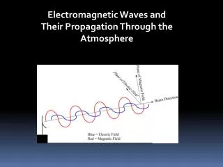
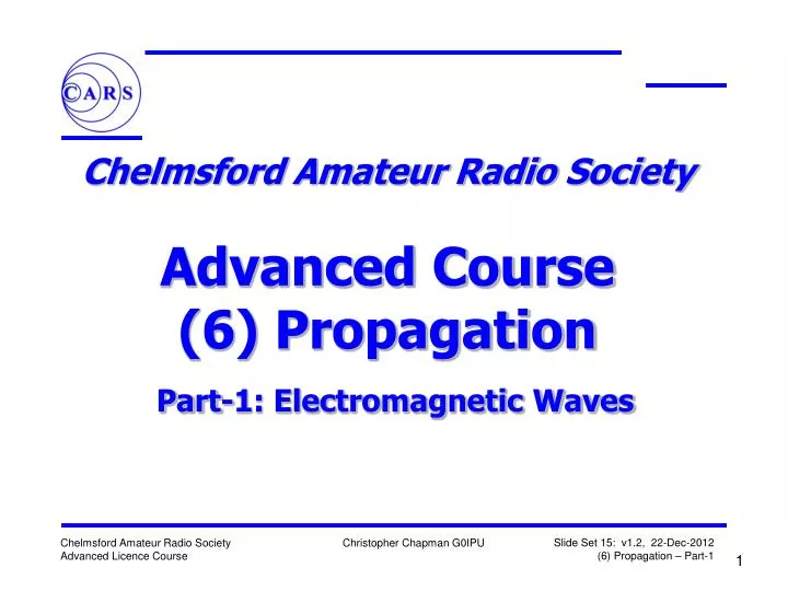
Chelmsford Amateur Radio Society Advanced Course (6) Propagation Part-1: Electromagnetic Waves. x. Electric Field, E. y. Direction of Propagation. z. Magnetic Field, H. Electromagnetic Waves. Electromagnetic radiation comprises both an Electric and a Magnetic Field

E N D
Chelmsford Amateur Radio Society Advanced Course(6) PropagationPart-1: Electromagnetic Waves
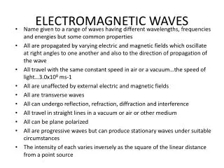
x Electric Field, E y Direction of Propagation z Magnetic Field, H Electromagnetic Waves • Electromagnetic radiation comprises both an Electric and a Magnetic Field • The two fields are at right-angles to each other, and the direction of propagation is at right-angles to both fields • The Plane of the Electric Field defines the Polarisation of the wave • The relationship between the magnitudes of the E and H fields is constant
EM Wave Fronts head-on Electric Field (E) Magnetic Field (H)
EM Wave Fronts head-on Electric Field (E) Magnetic Field (H)
Electromagnetic Radiation • In free space conditions Electro-Magnetic (EM) waves travelin straight lines and spread out • Both Power Flux Density (PFD) in W/m2 and Field Strength in V/m, drop with distance • Double the distance from an antenna and you willhalve the field strength, but also quarter the Power Flux Density (PFD), according to an inverse square law
EM Field vs Distance Rx Tx
Four units of area One unit of area D=1 D=1 Inverse Square Law forDistance and Intensity • Relationship between distance and intensity of electromagnetic radiation (rf or light) • Inverse square gives a 1/d2 reduction • Example • D= 1m - Intensity = 1 • D = 2m - Intensity = ¼ • Doubling the distance spreads same amount of energy over four times the area
D=1 D=1 D=1 Another PFD Example
v f l Velocity Of Propagation • Propagation velocity depends on the medium in which EM waves travel: • Free Space Maximum velocity • Air slightly less than free space and dependent on water vapour • Coax ~0.66 Times that of Free Space • Water far less, and lossy v = f . v is the speed of radio waves light :- v = 300,000,000 m/s f is the frequency in Hz. is the wavelength in metres For l /4 for 2m 300 /145.5 x 0.66 / 4 = Coax length 340.2mm
Vertical Antenna Horizontal Antenna Linear Polarisation • Transmit and receive antennas should have the same polarisation • To be efficient... • Otherwise, signal strength may be reduced by up to 32dB • Polarisation losses can be up to 5 S-points • Note that after travelling through the ionosphere, the polarisation may have changed significantly
Circular Polarisation • The E-field of the wave rotates as it propagates, with either: • Left-handed polarisation (LHCP) (anticlockwise from behind) as shown, or • Right-Handed polarisation (RHCP) (clockwise from behind) Electric Field, E Magnetic Field, H Direction of Propagation • Used for satellite comms where the orientation of the EM field from the satellite is indeterminate • Make sure you receive correct circular orientation or high polarisation losses will result
Helical Antennas for Circular Polarisation • 2.4 GHz Helical Antenna Designed for OSCAR 40 • Omni-directional QuadrifilarHelical RHCP antenna