Download
1 / 21
400 likes | 1.43k Vues
Differential Amplifiers. Differential amps take two input signals and amplify the differences (“good” signal) while rejecting their common levels (“noise”) Normal-mode input: differential changes in the input signals Common-mode input: both inputs change levels together

E N D
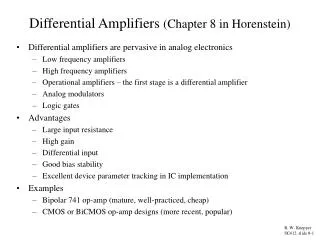
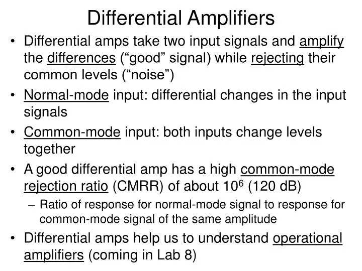
Differential Amplifiers • Differential amps take two input signals and amplify the differences (“good” signal) while rejecting their common levels (“noise”) • Normal-mode input: differential changes in the input signals • Common-mode input: both inputs change levels together • A good differential amp has a high common-mode rejection ratio (CMRR) of about 106 (120 dB) • Ratio of response for normal-mode signal to response for common-mode signal of the same amplitude • Differential amps help us to understand operational amplifiers (coming in Lab 8)
Differential Amplifiers in Electrocardiography (Analog Electronics for Scientific Application, D. Barnaal, Waveland Press, 1989)
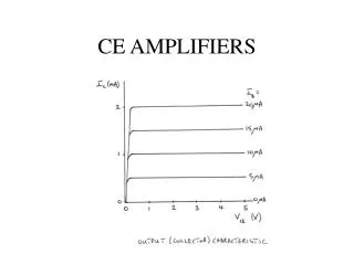
Differential Amplifier Construction (“single-ended” output) (“–” or “inverting” input) (“+” or “non-inverting” input) (The Art of Electronics, Horowitz and Hill, 2nd Ed.)
Differential Amplifier Construction • “Long-tailed” pair configuration: (The Art of Electronics, Horowitz and Hill, 2nd Ed.)
Differential Amplifier of Lab 6–1 output – input Q2 Q1 + input (Student Manual for The Art of Electronics, Hayes and Horowitz, 2nd Ed.)
Differential Amplifier Performance (Student Manual for The Art of Electronics, Hayes and Horowitz, 2nd Ed.)
Differential Amplifier Performance (Student Manual for The Art of Electronics, Hayes and Horowitz, 2nd Ed.)
Differential Amplifier Performance:Improving CMRR (Lab 6–1) (The Art of Electronics, Horowitz and Hill, 2nd Ed.)
+ input Single-Ended Input Differential Amplifier (Lab 6–1) output (not inverted) (The Art of Electronics, Horowitz and Hill, 2nd Ed.)
Example Problem 2.13 Verify that and . Then design a differential amplifier to your own specifications. Solution details given in class. (The Art of Electronics, Horowitz and Hill, 2nd Ed.)
Bootstrapping • “Standard” emitter follower biasing scheme: (The Art of Electronics, Horowitz and Hill, 2nd Ed.)
Bootstrapping (Lab 6–2) • “Bootstrapping” increases Zin at signal frequencies without disturbing the DC bias: (The Art of Electronics, Horowitz and Hill, 2nd Ed.)
Bootstrap Design • Want Thévenin resistance of bootstrap network at DC to be same as Thévenin resistance of bias voltage divider in original circuit (10k) • ChooseR3 = 4.7k • Then R3 + R1R2 = 10k R1R2 = 5.3k ≈ 5k • Choose R1 / R2 = 1 (same as original circuit) • Solve for R1 and R2 from the above R1 = R2 = 10k • Choose f3dB and calculate C2or choose C2 and calculate f3dB using C2 = 10 mF, f3dB = 3.2 Hz • We do the latter since we don’t know choice of f3dB • Similarly, choose C1and calculate f3dB,in • For C1 = 0.1 mF, f3dB,in = 16.9 Hz
Transistor Junction and Circuit Capacitance (The Art of Electronics, Horowitz and Hill, 2nd Ed.)
Miller Effect • Consider the following amplifier with voltage gain –G, with a capacitor connected between input and output: • The effective input capacitance becomes Ceff = C(1 + G) • According to the Miller model, the equivalent input circuit is: Ceff (Graphics from www.rfic.co.uk)
Miller Effect • Source impedance (Rsource) and Ceff form a low-pass filter with an f3dB smaller than without Miller Effect (CMiller = Ceff) (Student Manual for The Art of Electronics, Hayes and Horowitz, 2nd Ed.)
Defeating Miller Effect • Reduce Rsource (Rsource = 0 eliminates Miller Effect) • Arrange things so that base and collector of any one transistor do not head in opposite directions at the same time (Student Manual for The Art of Electronics, Hayes and Horowitz, 2nd Ed.)
Defeating Miller Effect (Lab 6–3) • Cascode circuit (Student Manual for The Art of Electronics, Hayes and Horowitz, 2nd Ed.)
Beating Miler Effect • Single-ended input differential amplifier (Student Manual for The Art of Electronics, Hayes and Horowitz, 2nd Ed.)
(Lab 6–4) Darlington Connection IC VB≈ 1.2 V VC IB ≈ 0.6 V VE = 0 V (Student Manual for The Art of Electronics, Hayes and Horowitz, 2nd Ed.)
(Lab 6–5) Superbeta Transistor Superbeta transistor used in Lab 6–5 (The Art of Electronics, Horowitz and Hill, 2nd Ed.)