Download
1 / 23
350 likes | 1.05k Vues
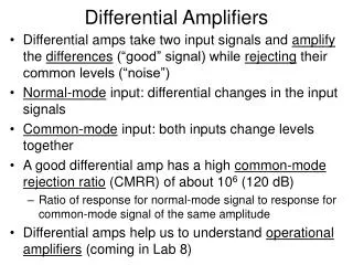
Differential and Multistage Amplifiers. Examples: BJT Differential Pair Small Signal Model Biasing Current Mirror. HW due Friday (10/18) 6.39,6.61,6.71,6.80. Example:. For BJT differential pair configureation, find v d such that:. i C1 =99% I i C1 =95% I i C1 =9 i C2.

E N D
Differential and Multistage Amplifiers Examples: BJT Differential Pair Small Signal Model Biasing Current Mirror October 15, 2002
HW due Friday (10/18) 6.39,6.61,6.71,6.80 October 15, 2002
Example: For BJT differential pair configureation, find vd such that: • iC1=99% I • iC1=95% I • iC1=9 iC2 October 15, 2002
Use equivalence For b=100, iC=aiE, a=100/101 a) b) c) October 15, 2002
Biasing in BJT Integrated Ckts • For what value of b would current mirror have a gain error 1%, 0.1 % • Imperfection due to base current diverted from reference current IREF October 15, 2002
Effect of b on BJT Curr. Mirror • Analysis of the current mirror taking into account the finite of the BJTs October 15, 2002
Current Steering Circuits • Generation of a number of cross currents • Q5 and Q6 in parallel, combination forms mirror with Q1. I3=2IREF • Q4 forms mirror with Q2. October 15, 2002
A current mirror with base-current compensation. • Improve dependence of I0 on b, why? • Error in mirror gain ckt as a result • How? Q3’s emitter supplies base currents of Q1 and Q2 October 15, 2002
The Wilson current mirror. By adjusting b, we can set output current to be a closer to IREF October 15, 2002
a) Q1 is diode connected, b1 does not matter b) Q2 with low b2, increases IO c) For high b3, , IO increases d) If one uses, b1= b and b2=(1-k) b and b3=(1+k) b, where k=1/2b, IO equals IREF Wilson current mirror features October 15, 2002
The Widlar current source. • Emitter resistance added to current mirror October 15, 2002
For constant current IO=10uA, determine values of resistors in collector (and emitter for Widlar source). Let VBE=0.7V at 1mA. current source ckt: Widlar ckt: Example 6.2 October 15, 2002
Example 6.3/ Opamp Ckt. • DC analysis shown on fig. • (start w/ Q9) • Rid • Av • RO October 15, 2002
For input resistance look at 1st stage. 1st stage gain, consider input resistance of second stage. Method October 15, 2002
A differential amplifier with an active load. Load is Q3 and Q4 October 15, 2002
Small-signal model of the differential amplifier October 15, 2002
Cascode amp. differential half circuit. The differential form of the cascode amplifier October 15, 2002
A cascode differential amplifier with a Wilson current-mirror active load October 15, 2002
MOSFET differential pair. October 15, 2002
MOSFET differential pair Normalized plots of the currents in a MOSFET differential pair. Note that VGSis the gate-to-source voltage when the drain current is equal to the dc bias current (I/2). October 15, 2002
MOS current mirrors (a) basic, (b) cascode, (c) Wilson, (d) modified Wilson. October 15, 2002
Basic active-loaded amplifier stages (a) bipolar; (b) MOS; (c) BiCMOS obtained by cascoding Q1 with a BJT, Q2; (d) BiCMOS double cascode. October 15, 2002
Voltage gain of the active-loaded common-source amplifier versus the bias current ID. Outside the subthreshold region, nCox = 20 A/V2, = 0.05 V-1, L = 2 m and W = 20 m. October 15, 2002