Download
1 / 29
290 likes | 463 Vues
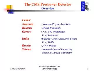
In situ performance of the CMS Preshower Wojciech BIALAS, CERN on behalf of CMS ECAL group. Topics. Location of the CMS Preshower Detector assembly & installation Commissioning & final sign-off statistics Noise & common-mode levels B field influence Summary. Preshower is part of

E N D
In situ performance of the CMS Preshower Wojciech BIALAS, CERN on behalf of CMS ECAL group
Topics • Location of the CMS Preshower • Detector assembly & installation • Commissioning & final sign-off statistics • Noise & common-mode levels • B field influence • Summary
Preshower is part of Electromagnetic Calorimeter - But is really an independent detector Only in the endcaps Location of CMS Preshower (“ES”) Slide from D.Barney see LECC 2005 talk
feedthrough(s) remark: all services/readout/power go through very confined space Preshower disk structure Remark: electronics is divided in two Dees, so it can be mounted, unmounted without opening of beam pipe see LECC 2005 talk
20cm 8 cm Transverse structure of CMS Preshower see LECC 2005 talk Slide from D.Barney
Transport from CERN (Meyrin) to CMS (Cessy) Transport in winter: Protective atmosphere
Installation Very limited time slot. Preshower is only CMS detector to be assembled in place
Tight schedule Mechanical installation: • ES+: moving Dees to platform: 5/3, ES in final position: 13/3: 7 working days • ES-: moving Dees to platform: 19/3, ES in final position: 27/3: 7 working days Services connection and testing fibres (reflection): • ES+: 18/3 to 26/3: 9 working days • ES-: 19/3 to 3/4: 5 working days First commissioning: • ES+: 26/3 to 6/4: 9 working days • ES-: 6/4 to 8/4: 3 working days slide from Wolfgang Funk
All ready Last CMS detector installed
Commissioning – 1st phase, immediately after installation Commissioning of Detector Control System: Temperature- & humidity-monitoring. Commissioning of N2 system Interlock tests to LV/HV Commissioning of cooling system Commissioning of LV system (sense wires, regulator inhibits) Commissioning of HV system (dark currents) Start local DAQ read-out and problem finding/solving (control-rings, data) Test of channel Btoken rings. Commissioning of heating and its monitoring (windows, drums, pipes) Final check-out after all mechanical work around Preshower is finished (e.g. w.r.t ECAL-Endcap). slide from Wolfgang Funk
Temperature map • Readout all DCU’s on board for temperature map. • Plot shows ladder temp after 2 hours power-on • Temperature low to high : Dark-Green, light green, yellow, orange then red • Average at 25.9℃ with spread of 0.8 ℃ slide from Rong-Shyang LU
Pair of unbiasedmicromodules Commissioning - 2nd phase Wolfgang Funk – CERN PH/CMX 22/04/2009-CMS-plenary
Commissioning - summary local DAQ ES+:Out of 68608 strips, 64 strips are not biased and 66 strips are slightly noisy (RMS > 15 ADC = 2.5 x average noise): 99.81% is working perfectly ES-:Out of 68608 strips, 1 strip is not connected to PACE (already like this in assembly) and 33 are slightly noisy (RMS > 15 ADC): 99.95% is working perfectly Combined: 99.88% is working perfectly! • Most of the front-ends are in the same good state as during assembly phase • One pair of the sensors can’t be biased, perhaps due to short circuit between sensor and ground or HV channel connectivity failure
Noise level in high gain mode (HG) Preshower operates in high gain mode for in-situ calibration with minimum-ionizing particles (MIPs) The total noise is around 6.6 ADC counts (intrinsic noise ~5.6 ADC counts) The MIP value is around 50 ADC counts in this mode PRELIMINARY
Noise levels in low gain mode (LG) Preshower operates in high gain for normal CMS physics data taking The total noise is around 3.1 ADC, while intrinsic noise around 2.5 ADC The MIP value is around 9 ADC in this mode PRELIMINARY
Preshower recorded cosmic particles (Aug. 09) One cosmic trigger event
Energy deposit of MIP in the detector • Cosmic particles come asyncronously • to machine clock i.e. in 25 ns window • Use thoeretical pulse shape to • fit 3 samples per event • 2. Extract and histogram peak value Preshower Si active sensor depth is around 320 um
B field infuence PRELIMINARY • Apart from a short-circuited sensor, we have masked 68 channels when B=0 and 126 channels when B=3.8T. (ES has total of 137,216 channels) • A channel is masked in HG if total-noise > 15 ADC. (1 MIP ~ 50 ADC) • We have also observed pedestal change with B-on. Therefore, we will need to maintain 2 set of pedestals values. ES+ Boff - Bon ES- slide from Rong-Shyang LU
B fieldinfluence – no change of noise PRELIMINARY ES- ES+ Boff - Bon front front ES- ES+ rear rear slide from Rong-Shyang LU
Summary • CMS Preshower detector successfully installed and commissioned • Measurement results shows performance as expected, fulfilling specification requirements • Detector is ready for LHC re-start • More studies are need for : • B field influence, long term stability, calibration and optimalisation of front-end parameters, timing-in with particles from LHC
B field influence • Pedestal change shown in geometry of ES+ endcap.
one micro-module on baseplate Note the front-end hybrid PCB supporting the PACE3, a DCUF for PACE3 calibration purposes and an embedded polyimide cable containing all connectivity (analogue, digital, powering)
on detector off detector Readout Path FPGA K chip K chip Optical Receivers FPGA SubdetectorEvent Builder K chip K chip K chip Kchip PACE ADC TTCrx GOH Slow Control & Fast Timing Signals I2C Reset Clk L1 TTCrx Control Path CCU I V I2C CCU DCU CCU CLK & T1 logic CCU FastTiming CCU CCU, PLL, QPLL VME interface TTCmodules Slow Control Front-End Control ASICs FEC-CCS Board re-use as much of others development as possible Readout and Control Architecture (via S-LINK) Front-End Readout ASICs ES-DCC Ring controllers slide from K.Kloukinas
Readout/Control • Readout/Control (on detector) • 4288 micromodules • 502 system motherboards (4 types) • Readout (off detector) • 1208 optical fibres @800Mbit/s • 40ES Data Concentrator Cards • Control (off detector) • 16 FEC-CCS cards (populated with 3x FEC-mezzanine) • 48 control rings (384 control optical fibers) • TTC (timing, trigger and control) • 1 LTC card + 2 TTCci cards + 1 TTCex (inside ECAL TTC crate)
Low voltage system • Power supplies based on CAEN EASY system • Separate power distribution for analog and digital parts, 50 pieces of A1025 per Dee, ie 200 in total • Straight (no twisted), no shielded cables in cable trays • Voltage sensing up to feedthroughs (cables twisted) • Separate inhibit lines for analog and digital part ST voltage regulators for all motherboards • No low imp. DC paths to Preshower vessel, all board connected to protective earth via 470 ohm resistor (starpoint) • One Control Ring motherboards share common DGND at feedthrough level to minimize CM between motherboards, that may cause control ring to malfunction