Download
1 / 47
480 likes | 631 Vues
I/O Devices and Connections. Board I/O. I/O Interface Serial/Parallel Asynchronous/Synchronous Example: Universal Asynchronous Receiver/Transmitter (UART) I/O Devices D isplays 7-Segment Display LCD T imers and counters

E N D
Board I/O • I/O Interface Serial/Parallel Asynchronous/Synchronous Example: Universal Asynchronous Receiver/Transmitter (UART) • I/O Devices Displays 7-Segment Display LCD Timers and counters A/D D/A converter Keyboards
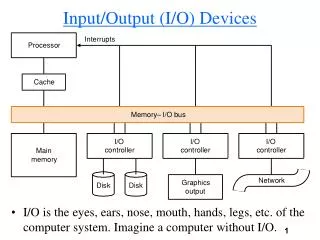
I/O Interface/Connector • Responsible for moving data from CPU/Memory to I/O Devices Master Processor Memeory Input Output
Component of I/O Interface • Transmission Medium • Communication Port • Communication Interface • I/O Controller • I/O Buses • Master Processor Integrated I/O
Duplicity • Simplex • Half duplex • Full duplex
Connections • Wired • Serial Communications • Parallel Communications • Wireless • Infrared • Radiowave
Serial/Parallel Asynchronous/Synchronous • Serial: Data are transmitted bit by bit in a single data line • Parallel: Data are transmitted in multiple bits simultaneously ( usually in multiple of byte ) • Asynchronous: No external synchronous signal needed for data synchronization, need start and stop signal included in data transmission • Synchronous: Need external synchronous signal
Serial communication • Single data wire • Words transmitted one bit at a time • Higher data throughput with long distances • Less average capacitance, so more bits per unit of time • Cheaper, less bulky • More complex interfacing logic and communication protocol • Sender needs to decompose word into bits • Receiver needs to recompose bits into word • Control signals often sent on same wire as data increasing protocol complexity
Serial communication parameters • Baud (bit) rate. Number of symbols transmitted per second • Number of bits per character. Number of bits for representing a symbol • Parity/no parity. • Even/odd parity. • Length of stop bit (1, 1.5, 2 bits).
Example: UART (Serial, Asynchronous) • Universal asynchronous receiver transmitter • provides serial communication. • Usually integrated into standard PC interface chip.
Parity check • Data transmitted: X1,X2,X3: bits • Even parity bit: X1 xor X2 xor X3 • Odd parity bit: ~(X1 xor X2 xor X3)
Serial protocols • I2C (Inter-IC) • Two-wire serial bus protocol • Serial data line (SDA) • Serial clock line (SCL) • Developed by Philips Semiconductors nearly 20 years ago • Data transfer rates • up to 100 kbits/s and 7-bit addressing (i.e., 128 devices) possible in normal mode • 3.4 Mbits/s and 10-bit (i.e., 1024 devices) addressing in fast-mode
Serial protocols • CAN (Controller area network) • All nodes can hear the message, each node filters the messages by itself • Protocol for real-time applications • Developed by Robert Bosch GmbH • Originally for communication among components of cars • Data transfer rates up to 1 Mbit/s and 11-bit addressing
Serial protocols • FireWire (a.k.a. I-Link, IEEE 1394) • High-performance serial bus developed by Apple Computer Inc. • Designed for interfacing independent electronic components • e.g., Desktop, scanner • Data transfer rates from 100,200,400 Mbits/s, (new revision up to 800, 1600MBits/s) • Maximal distance between two devices are 4.5 meters • Maximal number of devices 63 • Plug-and-play capabilities • (revise)3.2 gbps
Serial protocols • USB (Universal Serial Bus) • Invented in 1995 • A serial bus that supports up to 127 devices • Plug and play • Four wires: Vbus, GND, D+, D- • D+ high D- low 1 • D+ low D- high 0 • Data rates: • 12 Mbps for increased bandwidth devices • 1.5 Mbps for lower-speed devices (joysticks, game pads) • 480 Mbps (USB 2.0) • USB 3.0 • 4.8Gbps
A Typical USB System • One and only one host • Control media access • Hub • Enable multiple devices to be connected to the same USB bus • Detect attachment and detachment of devices and power management • Manage both high and low speed device • Other USB devices • Self powered/Bus powered • Full-speed/low-speed devices
Parallel communication • Multiple data, control, and possibly power wires • One bit per wire • High data throughput with short distances • Typically used when connecting devices on same IC or same circuit board • Bus must be kept short • long parallel wires result in high capacitance values which requires more time to charge/discharge • Data misalignment between wires increases as length increases • Higher cost, bulky
CPU memory device CPU bus bus interface high-speed bus DMA controller intr ctrl timers low-speed bus bus interface device Bus Connections • Data transfer between processors, memories, and I/O devices • Usually implemented using buses • Bus • What/Why bus hierarchy
rd'/wr Processor Memory enable addr[0-11] data[0-7] bus bus structure A simple bus • Bus • Set of wires with a single function • Address bus, data bus • Or, entire collection of wires • Address, data and control • bus protocol: rules for communication
rd'/wr enable addr data tsetup tread read protocol rd'/wr enable addr data tsetup twrite write protocol Timing Diagrams • Most common method for describing a communication protocol • Time proceeds to the right on x-axis • Control signal: low or high • May be active low (e.g., go’, /go, or go_L) • Use terms assert (active) and deassert • Asserting go’ means go=0 • Data signal: not valid or valid • Protocol may have subprotocols • Called bus cycle, e.g., read and write • Each may be several clock cycles • Read example • rd’/wr set low,address placed on addr for at least tsetup time before enable asserted, enable triggers memory to place data on data wires by time tread
Parallel Connection • PCI Bus (Peripheral Component Interconnect) • High performance bus originated at Intel in the early 1990’s • Standard adopted by industry and administered by PCISIG (PCI Special Interest Group) • Interconnects chips, expansion boards, processor memory subsystems • Data transfer rates of 133 Mbits/s and 32-bit addressing • Later extended to 64-bit while maintaining compatibility with 32-bit schemes • Multiplexed data/address lines
About PCI-x and PCI-Express • PCI-x • Designed by IBM, HP and Compaq • PCI extended, enhanced PCI bus to as much as 4 Gbps • PCI-Express • Point-to-point connection • A two-way serial connection • Data is transmitted through two pairs of wires called lane • Each lane has transfer rate 2.5Gbps or approx. 200MB/s data rate • Multiple lanes can be used • Plug and play
Wireless communication • No need for physical connection • Infrared (IR) • Electronic wave frequencies just below visible light spectrum • Turning on/off diode generates 1/0 • Infrared transistor detects signal, conducts when exposed to infrared light • Cheap to build • Needline of sight, limited range • Radio frequency (RF) • Electromagnetic wave frequencies in radio spectrum • Analog circuitry and antenna needed on both sides of transmission • Line of sight not needed, transmitter power determines range
Wireless protocols • IrDA • Short-range point-to-point infrared data transmission • Zero – one meter • Created and promoted by the Infrared Data Association (IrDA) • Two modes • Transfer rate of 9.6 kbps and 16 Mbps • Becoming available on popular embedded OS’s
Wireless protocols • Bluetooth • New, global standard for exchanging data via wireless within short distance • Connection can be established when within 10 meters of each other • Based on low-cost, short-range radio link to remove the cables • No line-of-sight required • e.g., Connect to printer in another room
Wireless Protocols • IEEE 802.11 • Proposed standard for wireless LANs • Layered protocol • Specifies parameters for PHY and MAC layers of network • provisions for data transfer rates of 11, 54, 600 Mbps • operates in 2.4 to 2.4835 GHz frequency band (RF)or 300 to 428,000 GHz (IR)
Timers and counters • Very similar: • Registers to hold the current value; • An increment input that adds one to the current register value. • Timer • Connected to a periodic clock signal • Counter • Connected to more general (periodic/aperiodic) signals
Watchdog timer • Watchdog timer is periodically reset by system timer. • If watchdog is not reset, it generates an interrupt to reset the host. host CPU interrupt watchdog timer reset
A/D and D/A converters • A/D converter (ADC) • The control signal requires sampling the analog signal and converting it to digital form (binary) • D/A converter (DAC) • Convert the digital signal to the analog signal
N1 N2 N3 k_pressed N4 M1 M2 M3 M4 4 key_code key_code keypad controller N=4, M=4 Keyboard • An array of switches • Button bouncing and debouncing
Key Bouncing • The mechanical contact to make or break an electrical circuit generates bouncing signal • Debouncing
LED • Light Emitting Diode • Use resistor to limit current: Output Digital Logic
7-segment Display • Can display hex numbers (0-9,A-F) • Widely used in digital clock, temperature controller,etc
E communications bus R/W RS DB7–DB0 8 microcontroller LCD controller LCD display • Liquid crystal display • The digit input activates the display elements
LCD Parameters • Resolution • Horizontal and vertical size • Dot pitch • Distance between two adjacent pixel • Response time • Time to change the color or brightness • Refresh rate • Number of times the data is drawn • Others • View angles, contrast ratio, aspect ratio, etc
Types of high-resolution display • Cathode ray tube (CRT) • Liquid crystal display (LCD) panels • Plasma, etc.
Touchscreen • Includes input and output device. • Input device is a two-dimensional voltmeter:
voltage Touchscreen position sensing ADC
Summary • Connections • Wired connections • Serial • RS-232, I2C, CAN, Fire Wire, USB, PCI-Express • Parallel • Bus, PCI, PCI-x • Wireless connections • IrDA, Blue Tooth, IEEE802.11 • I/O devices • Timer/counter, ADC/DAC, keyboards, display