Download
1 / 13
140 likes | 273 Vues
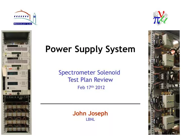
Power Supply System . Spectrometer Solenoid Test Plan Review Feb 17 th 2012. John Joseph LBNL. Simplified PS System Block Diagram. Slow Control Functions Ramp Rates Contactor switching for ramp cycles Status Monitoring Voltage Current Temperature Direct control of all PS Units

E N D
Power Supply System Spectrometer Solenoid Test Plan Review Feb 17th 2012 John Joseph LBNL
Simplified PS System Block Diagram • Slow Control Functions • Ramp Rates • Contactor switching for ramp cycles • Status Monitoring • Voltage • Current • Temperature • Direct control of all PS Units • QDS Functions • Real time Quench Detection • Contactor switching for fast discharge • Real time system status monitoring MagnetCoil Power Supply Rack Power Supplies for the Center Coil & Matching Coils Power Supply Slow Control System Quench Detect System
LBNL/MICE: DC PATH [As Built] • Added 5 contactors to system • HTS Lead protection during fast discharge
Energy Absorber Assemblies Plumbing for Water Cooling of Energy Absorbers • 4 Energy Absorbers • Required for slow ramp down of coils • 2 diode assemblies per absorber circuit • 1 DA always dissipating power into air & water • 2 water circuits available for cooling
POWER SUPPLY RACK CONFIGURATION FRONT VIEW K2 MS2 300A PS K1 MS1 300A PS EC1 60A PS K7 EC2 60A PS K8 CS 60A PS K3 EA - DA3 EA - DA4 K6 EA - DA2 EA - DA1
Summary of Changes Implemented @ LBL • Redesigned system to improve HTS Lead protection • Additional contactors to isolate coils from power supplies during fast ramp down and enable in-cryo coil protection • Adding 2nd Solid State Relay to handle increased Contactor pickup current • Reconfigured rack to optimize DC cabling • Improved physical separation of AC and DC wires • All Contactors physically close to associated supplies • Moved all AC wiring above water cooling circuits • Replacing 15 VDC PS with 24 VDC PS for interlock circuits • Replaced all control and monitoring wiring • Bundled twisted pair
Requires 2nd Solid State Relay • ~35A of in-rush when coils energized to close contactors • Replacing 15 VDC PS with 24 VDC PS • Standard for Interlock systems • Requested by RAL • Potential to stagger Contactor on signal to reduce instantaneous power peak
Power Entry, Control, and Monitoring TB1 208 VAC 3-PHASE Power Entry TB4 Status Monitoring • K1 - VDROP • K2 – VDROP • K3 – VDROP • K4 - VDROP • K5 - VDROP • K6 - VDROP • K7 - VDROP • K8 – VDROP • CONTACT STATUS • PS TEMP SENSORS TB4 Status Monitoring TB2 PS Voltage Monitoring SSR, TB3, PS6 Interlock & Contactor Control
Additional Changes per Collaboration Discussion • Rewire Temp Sensors to move over-temp reaction control to Slow or Fast DAQ • Overheating of Energy Absorbers should be slow ramp down not fast discharge • Add Emergency Off switch to front and back of racks • Contactor Aux Contacts indicate • All Contactors closed • One or more Contactors open • Currently only indicates if all are open
Power Requirements for Test • Loads on 3 Phase 208 VAC • 300A Power Supply for the Center Coil (15A @ 3.3kW) • 300A Power Supply for Matching Coil 1 (80% efficiency min) • 300A Power Supply for Matching Coil 2 (80% efficiency min) • Loads on Single Phase 208 VAC • 6 Contactor Coils requiring 970VA for Pickup • 2 Contactor Coils requiring 245VA for Pickup • 24VDC, 60 Watt, Power Supply for system Interlock circuits • Loads on 120 VAC • 60A Trimming Power Supplies for the End Coils (Qty 2) • 850 VA per Unit • Power Supply Controllers for the 300A Units (Qty 2) • 50 VA per Unit
Tasks to Complete • Complete remaining assembly tasks on the rack to be used at Wang • Implement RAL recommendations • Complete the final Documentation package • Final Schematics & Wire Lists • Configuration Drawing • Low Current Functionality Testing of all System Components • Avoid connecting water circuits • Load PS outputs with shorting cables • Decision on Assembly of 2nd Power Supply Rack • Requested to go directly to RAL • New rack configuration is under consideration