Download
1 / 38
410 likes | 708 Vues
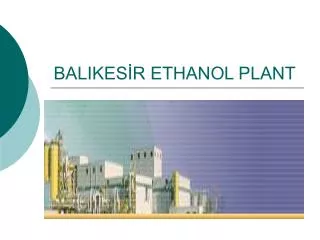
Equipments Design Ethanol plant. Prof. M. Fahim Eng. Yousef Ismael. Done By: Mona Al-Khalaf. Agenda. Distillation Columns Design( T-104) . Compressors Design ( K-101)&( K-102) . Heat Exchangers Design( E-105). Distillation Columns. To produce main product Ethanol.

E N D
Equipments DesignEthanol plant Prof. M. Fahim Eng. Yousef Ismael Done By: Mona Al-Khalaf
Agenda • Distillation Columns Design( T-104). • Compressors Design ( K-101)&( K-102). • Heat Exchangers Design( E-105).
Distillation Columns To produce main product Ethanol
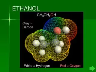
Distillation Column T-(104) design Distillation Columns: • Is a separation unit based on the difference between a liquid mixture and the vapor formed from it. Objective: To separate of ethanol from propanol.
Number of trays Shortcut method: • It's used To determine the minimum number of trays • the method is also called the Fenske equation as follows: Nm =log (Xlk/XHk)d * (XHk/XLk)b /(logαLK) Average relative volatility of the light key with respect to the heavy key, where αLK=(αlD*αlW)^.5 αi=(Pi/PHK) Pi=Partial pressure for i key. PHK= Partial pressure for heavy Key.
Distillation Column Design. • Assumptions: • Column Efficiency=70%. • Tray spacing=0.55. • Flooding Percentage at maximum flow rate=85%. • Percent of downcomer area of total area=12%. • Hole area( 10% of Active area). • Weir height=50mm. • Hole diameter =5 mm. • Plate Thickness=5mm. • Turn down Percentage (70%) • Material of column is carbon steel. • Good Design: • actual minimum vapor velocity should be greater than Uh( vapor velocity). • Back-up in downcommer (hb) less than tray spacing to accept tray spacing. • Residence time exceeds 3 secs.
Main design procedures: For column diameter 1-calculate the liquid –vapors flow factor for top and bottom FLV= LW / Vw * (ρv / ρl) ½ Where:- LW = liquid mole flow rate in kmol /h Vw = vapors mole flow rate in kmol / h ρv = density of the vapors in kg / m³ ρl = density of the liquid in kg / m³
2-from fig 11.27 get constant for the top and the bottom top k1 and bottom k1 3-calculate the correction factor for top and the bottom K = (σ / 0.02) ^0.2 * K1 Where:- σ = liquid surface tension in N/m 4-calculate the flooding velocity for top and bottom Uf = K *( (ρl –ρV) / ρ v)½ Where:- Uf = flooding vapour velocity in m/s K= constant obtain from fig 11.27 ρl = density of liquid in kg / m³ ρv = density of vapour in kg / m³
5-Assume the flooding percentage is 85% at max flow rate for the top and the bottom UV = 0.85 * Uf 6-calculate the net area for the top and the bottom An = Vmax / UV Where: An = net area in m² V = Volumetric flow rate in m³ / s UV = vapour velocity in m/s
7-Assume as first - trail take down comer as 12% of total cross sectional area for the top and the bottom Ad = An / 0.88 Where: Ad = area of the down comer in m² An = net area in m² 8-calculate the diameter for the top and the bottom D = ((4 /3.14) * Ad) ½ Where: D = Diameter in m Ad = area of the down comer in m²
Double pass plate is used (from figure 11.28) 9-calculate the liquid flow pattern Max liquid volumetric flow rate = Lm *MW / ρL * 3600 10-calculate the areas Ac = (3.14 / 4)*D² Where: Ac = total cross sectional area in m² Ad = 0.12 * Ac Where: Ad = area of the down comer in m²
An = Ac –A d Where: An = net area in m² Aa = Ac – 2Ad Where: Aa = active area in m² Ah = 0.1 * Aa Where: Ah = hole area in m²
Use fig 11.31 to get LW / Dc 11- 12-Assume weir length = 50 mm Hole diameter = 5 mm Plate thickness = 5 mm 13-Check weeping how max = 750 * (Lwd max / (LW*ρl)) ^2/3 how min = 750 * (Lwd min / (LW*ρl)) ^2/3 At min rate = hw + how Where:- how=Weir liquid crest 14-calculate the weep point Uh = k2- 0.9 *(25.4-dh)/ρv½ Where: Uh = min vapor velocity through the hole in m/s Dh = hole diameter in m K2 = constant from fig 11.30
15-calculate the actual vapour velocity Calculate the actual vapour velocity = min vapour rate / Ah 16-Calculate the pressure drop UH = Vv / Ah Where: Vv = volumetric flow rate in m³ / s Ah = net area in m²
HD = 51 * (Uh/ C0)² * ρ V / ρL Where: Hd = dry plate pressure drop Uh = min vapour velocity in m/s Co is the orifice coefficient from figure (11.34) Hr = 12.5E3 / ρL Where: Hr = residual head Ht = HD + HW + HOW + HR Where: Ht = total pressure drop in mm
17-down comer liquid backup Hap = HW – 10 Aap = LW * hap *0.001 Where: Aap = area under apron Hdc = 166 * LW / (ρ l * Aap) Backup down comer Hb = hdc + ht + how max + hw
18-Calculate the residence time TR = (Ad * hb * ρ l) / lwd from figure 11.29 get ψ 19-Calculate the flooding percentage Flooding percentage = UV / uf * 100 20-Calculate the area of the hole A = (3.14 / 4 ) * (dh * 0.001 )² 21-Calculate number of hole Number of hole = A h / A
22-Calculate the thickness , Where: t: thickness of the separator in (in) P: operating pressure in Pisa ri: radius of the separator in (in) S: is the stress value of carbon steel = 13700 Pisa Ej: joint efficiency (Ej=0.85 for spot examined welding) C0: corrosion allowance = 0.125 23- calculate the cost
From fig. we get the Cost of one tray at year 1990 • And we can get the cost of one tray by use the fig or by use the law which is depend on the original cost(1990) • The cost of total trays=cost of one tray*actual stage number
Cost of distillation=cost of vessel+cost of total trays+cost of condenser+cost of reboiler.
Compressors Design:( K-101)&( K-102) Design two compressors.
Compressors • Compressor : • Is a gas compressor is a mechanical device that increases the pressure of a gas and naturally increases its temperature by reducing its volume. • Objective • To increase the pressure of feed before it's inters to cooler E(105) • To increase the pressure of feed before it's inters to cooler E(101)
Design Procedures and Equations: • Calculate the compression factor using the following equation: Where P1,2 is the pressure of inlet and outlet respectively (psia), And T1,2 is the temperature of the inlet and outlet respectively (R). (2) Calculate the work done in Btu/lbmol by: Where R is the ratio of the specific heat capacities (Cp/Cv). (3) Calculate the horse power, Hp using the following equation: Where M is the molar flow rate in lbmol/s.
(4)Calculate the efficiency of the compressor using the following equation: Where and Mw is the molecular weight of the gas in the stream and Cp is the specific heat capacity (Btu/lb.F). (5) Depending on the horse power we can decided which type of compressor we going to use and calculate its cost. (6) Finally calculate the cost of the compressor from www.matche.com by using horse power value. (7) Calculate the inflation rate cost from year 2007 to year 2009 from draw graph between (years and Nelson-Farrar refinery construction index), so we get linear equation (y=46.6785714x-91600.995).
Cooler ( E-105) (Heat Exchangers Design) Design of first cooler
a heat exchanger is a device made for efficient heat transfer from one fluid to another across a solid surface. • Objective • To cooled the feed stream and prepare it to inter the compressor(k-102)
Shell & Tube Heat Exchanger Design. • Assumptions: • For cooling the fluid, cooled water has been used. • Assuming value for overall heat transfer coefficient based on table 12.1 which =360, which should be closed to the calculated value. • The type of heat exchanger is shell and tube, while the material of construction is carbon steel. • Assume the outer=40, and the tube length=5.3. • Assume the inlet and outlet temperature and pressure for the water in the tube side. • Choose 25% baffle cut. • Because the inlet stream flow rate was very high, so we divided it in to three stream and the cost wasmultiply to three. • a good design : • The assumed overall heat coefficient has to be close to the calculated overall heat transfer coefficient., • The pressure drop in the tube side should be smaller value. • The pressure drop in the shell side should be smaller value.
Shell & Tube Heat Exchanger Design. Log mean Temperature Heat Load Where; ∆Tlm = log mean temperature differace T1 is temperature of inlet hot stream. (oC) T2 is the temperature of outlet hot stream. (oC) .t1 is the temperature of inlet cold stream. (oC) .t2 is the temperature of outlet cold stream. (oC). Where, Ft = the temperature correction factor Using one shell pass and two or more even tube passes
Shell & Tube Heat Exchanger Number of tubes Heat Transfer Area Assuming U from table12.1=360(W/m2 oC) Shell and Bundle diameter Where ; Nt is the number of tubes= Provisional area/Area of one tube.. K1, n1 are constants. do=Outside diameter (mm) Db is the bundle diameter (mm) Ds is the shell diameter. (mm)
Shell & tube heat exchanger Design Tube Side Heat Transfer Coefficient Shell side heat Transfer Coefficient Where is the density of fluid (kg/m3). is the thermal conductivity (W/m.C). is specific heat (kJ/kg.k). Re is the Reynolds number. Pr is the Prandtl number. Nu is the Nusselt number. is the convective heat transfer coefficient (W/m2.C). Where; .pt is the tube pitch (mm). .lB is the baffle spacing (mm). As is the cross flow area (m2) us is the velocity (m/s). de is the equivalent diameter for triangular arrangement (mm). jh is the heat transfer factor hs is the convective heat transfer coefficient (W/m2.C).
Shell & Tube Heat Exchanger Design. Overall Heat Transfer coefficient Shell Side Pressure Drop Thickness Tube side pressure Drop Where; D is the shell diameter in m Rj is internal radius in (in). P is the operating pressure in psi S is the working stress (psi). E is the joint efficiency
Cost of heat exchanger • We calculate the cost of heat exchanger at year 2007 based on Heat transfer area from (www.matche.com) and we can calculate the cost of heat exchanger at year 2009 by adding the inflation rate value (y=46.6785714x-91600.995, where (X) is the year) to the cost of heat exchangerat year 2007. • The cost of three heat exchanger= (cost of one heat exchanger) * (3)