Download
1 / 1
10 likes | 124 Vues
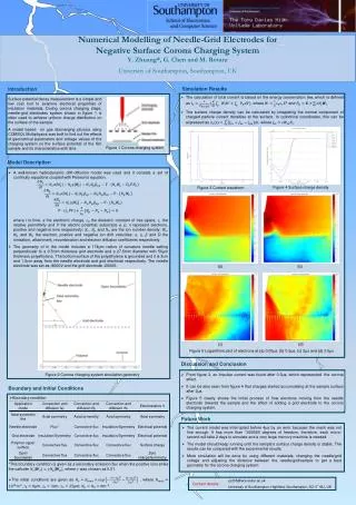
38 cm. 183cm. 1 st 2 nd stage. Amplifier schematic. Amplifier in module box. Non-irradiated/irradiated Agilent FE comparison. Si diode signal Si diode noise Gali-52 amplification. 44 m. BCM modules. ATLAS.

E N D
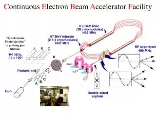
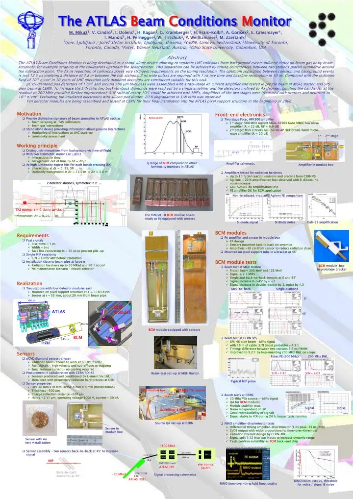
38 cm 183cm 1st 2nd stage Amplifier schematic Amplifier in module box Non-irradiated/irradiated Agilent FE comparison Si diode signal Si diode noise Gali-52 amplification 44 m BCM modules ATLAS Back-to-back Single diamond 0° single double BCM 45° Pixel Fotec FE (500 MHz) 200 MHz BWL S/N ~ 7.5:1 S/N ~ 9.2:1 Typical MIP pulse Sensor in module box ~100 kRad Sensor with Au test metallization ~100 m ~15 m electronics cavern ATLAS PP2 ~30 MRad Signal processing schematics ATLAS PIXEL MIP Back-to-back diamonds at 45° The ATLAS Beam ConditionsMonitor M. Mikuž1, V. Cindro1, I. Dolenc1, H. Kagan5, G. Kramberger1, H. Frais-Kölbl4, A. Gorišek2, E. Griesmayer4, I. Mandić1, H. Pernegger2, W. Trischuk3, P. Weilhammer2, M. Zavrtanik1 1Univ. Ljubljana / Jožef Stefan Institute, Ljubljana, Slovenia, 2CERN, Geneva, Switzerland, 3University of Toronto, Toronto, Canada, 4Fotec, Wiener Neustadt, Austria, 5Ohio State University, Columbus, USA Abstract The ATLAS Beam Conditions Monitor is being developed as a stand-alone device allowing to separate LHC collisions from background events induced either on beam gas or by beam accidents, for example scraping at the collimators upstream the spectrometer. This separation can be achieved by timing coincidences between two stations placed symmetric around the interaction point. The 25 ns repetition of collisions poses very stringent requirements on the timing resolution. The optimum separation between collision and background events is just 12.5 ns implying a distance of 3.8 m between the two stations. 3 ns wide pulses are required with 1 ns rise time and baseline restoration in 10 ns. Combined with the radiation field of 1015 n/cm2 in 10 years of LHC operation only diamond detectors are considered suitable for this task. pCVD diamond pad detectors of 1 cm2 and around 500 μm thickness were assembled with a two-stage RF current amplifier and tested in proton beam at MGH, Boston and SPS pion beam at CERN. To increase the S/N ratio two back-to-back diamonds were read out by a single amplifier and the detectors inclined to 45 degrees. Limiting the bandwidth at the readout to 200 MHz provided further improvement; S/N ratio of nearly 10:1 could be achieved with MIP's. Amplifiers of the two stages were irradiated with protons and neutrons to 1015 n/cm2. Evaluating the irradiated electronics with silicon pad diodes, 20 % degradation in S/N ratio was observed. Ten detector modules are being assembled and tested at CERN for their final installation into the ATLAS pixel support structure in the beginning of 2006. • Motivation • Provide distinctive signature of beam anomalies in ATLAS such as • Beam scraping at TAS collimators • Beam gas interactions • Stand alone device providing information about genuine interactions • Monitoring of interactions at LHC start-up • Luminosity assessment • Front-end electronics • Two stage Fotec HFK500 amplifier • 1st stage: 500 MHz Agilent MGA-62563 GaAs MMIC low noise amplifier (A = 22 dB, NF = 0.9 dB) • 2nd stage: Mini Circuits Gali-52 InGaP HBT broad-band micro-wave amplifier (A = 20 dB) • Amplifiers tested for radiation hardness • Up to 1015/cm2 reactor neutrons and protons from CERN PS • Agilent: ~ 20 % amplification loss observed with Si diodes, no noise increase • Gali-52: 0.5 dB amplification loss • FE amplifier OK for BCM application • Working principle • Distinguish interactions from background via time of flight • With two symmetric stations at ±Δz/2 • Interactions: in time • Background: out of time by Δt = Δz/c • At high luminosity expect hits for each bunch crossing (BX) • Interactions at Δt = 0, 25, 50 … ns • Optimally background at Δt = 12.5 ns ⇒ Δz = 3.8 m η range of BCM compared to other luminosity monitors in ATLAS 2 detector stations, symmetric in z X TAS events: t = 0, 2z/c; Δt=2z/c The total of 10 BCM module boxes ready to be equipped with sensors Interactions: Δt = 0, 25, … ns Δ • BCM modules • Fe amplifier and sensor in module box • RF design • Sensors mounted back to back on ceramics • Amplifiers ~10 cm from sensor to reduce radiation dose • Mounted on pixel support tube in a bracket at 45° • Requirements • Fast signals • Rise-time ~ 1 ns • Width ~ 3ns • Base line restoration in ~ 10 ns to prevent pile-up • Single MIP sensitivity • S/N ~ 10 for MIP before irradiation • Installation close to beam pipe at large η • Radiation hardness up to 50 MRad and 1015π/cm2 • No maintenance scenario – robust detector • BCM module tests • Beam test at MGH Boston • Proton beam 200 MeV and 125 MeV • Signal ≥ 2.3 MIPs • Single and back-to-back sensors at 0 and 45° • Signal increase 0->45° by ~ √2 • Signal increase in double-decker by 2, noise by 1.3 • Beam test at CERN SPS • SPS H8 pion beam – MIPs signal • with 16 m of cable:S/N (most probable) ~ 7.5:1 • Timing: difference between two stations 2.7 ns FWHM • Improved to 9.2:1 by implementing 200 MHz BWL on scope • Bench tests at CERN • 30 MBq 90Sr source; ~ MIPs signal • QA for BCM modules • Module stability tests • Noise independent of HV • Good reproducibility of signals • Signal stable to 4 % during 24 h, longer tests running • NINO amplifier-discriminator tests • Differential timing amplifier-discriminator (1 ns peak, 25 ns jitter) • LVDS output with width proportional to time-over-threshold • Radiation tolerant design by CERN-MIC • Signal split 1:12 into two inputs to increase dynamic range • Tests confirm suitability as BCM back-end chip BCM module box in prototype bracket • Realization • Two stations with four detector modules each • Mounted on pixel support structure at z = ±183.8 cm • Sensor at r ~ 55 mm, about 20 mm from beam pipe BCM module equipped with sensors • Sensors • pCVD diamond sensors chosen • Radiation hard – shown to work at > 1015π/cm2 • Fast signals – high velocity and cut-off due to trapping • Small leakage current – no cooling required • Procurement in collaboration with CERN RD-42 • Sensors produced and conditioned by Element Six Ltd. • Metallized with proprietary radiation hard process at OSU • Sensor properties • Size 10 mm x10 mm, active 8 mm x 8 mm (metallization) • Thickness ~500 μm • Charge collection distance ~220 μm • Holds ~ 2 V/ μm, operating voltage 1000 V, current ~ 30 pA • Sensor assembly – two sensors back-to-back at 45° to increase signal Beam-test set-up at MGH Boston BCM module box 30 MBq 90Sr source Signal Noise Scintillator & PMT Source QA set-up at CERN Amplitude FE output NINO output Pulse-width NINO count-rate vs. threshold for noise / signal & noise NINO time-over-threshold functionality