Download
1 / 20
200 likes | 298 Vues
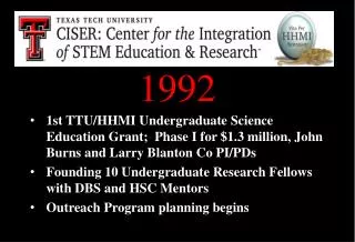
CSR Emission Studies in VUV/IR Ring NSLS. Stephen Kramer, VUV Ring Manager 1992-2002. Technical Design Parameters. NSLS VUV and Xray Light Sources Proposed in 1970’s VUV ops 1982, Xray ops 1984 with >2300 Users/year using >65 beam lines from Far-IR to Hard Xrays VUV /IR Ring Parameters.

E N D
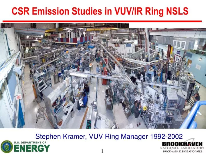
CSR Emission Studies in VUV/IR Ring NSLS Stephen Kramer, VUV Ring Manager 1992-2002
Technical Design Parameters NSLS VUV and Xray Light Sources Proposed in 1970’s VUV ops 1982, Xray ops 1984 with >2300 Users/year using >65 beam lines from Far-IR to Hard Xrays VUV /IR Ring Parameters
VUV Period for Achromatic Optics Peak x ~ 1.51 m,Doublet makes βx small in dispersion and large in ID making Touschek lifetime small due to septum edge
IR Developed in 1989 6 in 2004 e bolometer(lHe) UHV Source point Mirror M3 cone chop window MirrorsM1 and M2 lamellargratinginterferometer
FIR Port at end of Dipole U12IR extraction U11/U12/U12IR Two VUV ports ahead of FIR, at 7° and 22° into 45° dipole, ρ = 1.91 m dipole chamber shielding cut-off for CSR and ISR fc ~ 24 GHz or 0.8 cm-1
Threshold Current Microwave Instability Bunch length data showed a threshold of 100-120mA for Microwave threshold at 745-800 MeV with Zbb/n ~ 1.8Ω and Spear scaling
Energy Dependence Microwave Instability The microwave threshold based on the Keil-Schnell Criterion
FIR Measurements of Spectra in 2-FIR Interference model for line structure in both ISR and CSR pattern with Δf ~ 1cm-1 spacing in two similar beamlines with different spectra ranges
Reflection from Dipole Chamber Outer Wall Could give a Sin2(2π f Δt) modulation to broadband ISR and CSR spectra ΔL~1cm or frequency spacing ~ 30 GHz Slope =2*sin(/2) ~ 0.4 Zero at ~30 GHz due to 180 degree phase shift at metal boundary
FIR Beam Coupler Has Cut Off ~30GHz Optical coupling to FIR port cuts off below ~30 GHz, 4” beam window available 90° Metal paddle to block FIR beam deflects microwaves down to window (ring VC limits) Dipole chamber cut-off waveguide frequency TE1,0 ~ 2GHz and TM1,1 ~ 4 GHz Microwave measurements confirm CSR peak ~42GHz ~1.4 cm-1 peak “C”, but see two more “A and B” Microwave horns for deflected light
Time Dependence of Peak Signals • B and C are prompt signals from the bunch limited by RF diode ~1GHz BW Revolution time To=170nsec • A signal 60 -100ns wide delayed by ~30-50ns from bunch
Power in Peaks versus Bunch Current • C &B signal linear for Io < Ith • C&B quadratic for Io > Ith • C&B Ey polarization • A signal always quadratic or higher beam impedance P~ I2 * R • A signal unpolarized
A Peak - Wakefield Emission From Bellows Vacuum bellows shield with Cu convolutions 1cm gave calculated beam impedance RF microwave and charge modulation shows 6.5GHz but ~4GHz at current below Threshold current
Micro-bunching measured with SC Triggering the Streak Camera on the A peak signal yielded consistent micro-structure with 150 psec modulation or 6.5 GHz, no other micro-bunch was significant.
Warnock & Venturini CSR Signal + Interferr. Adding a 0.8cm delay for reflection from outer dipole chamber wall
Interference Pattern from Different Ports U10IR port has only 20° of bend ahead of port not > 23° for Interference pattern from dipole. However pattern from upstream dipole less clear.
Summary and Status • VUV ring CSR emission above Microwave Instability which scales with energy and α1 • CSR and ISR show interference pattern from outer wall broader than WG modes but related • Shielded ISR and CSR cut-off frequency appears to be ~ 24 GHz but sharp cutoff, allows the 6 GHz wakefield signal to be observed • Wakefield power growth proceeds CSR, shows clear micro-bunching above CSR threshold • FIR users not interested in stable CSR emission but maybe hard to achieve without RF upgrade