Download
1 / 25
250 likes | 260 Vues
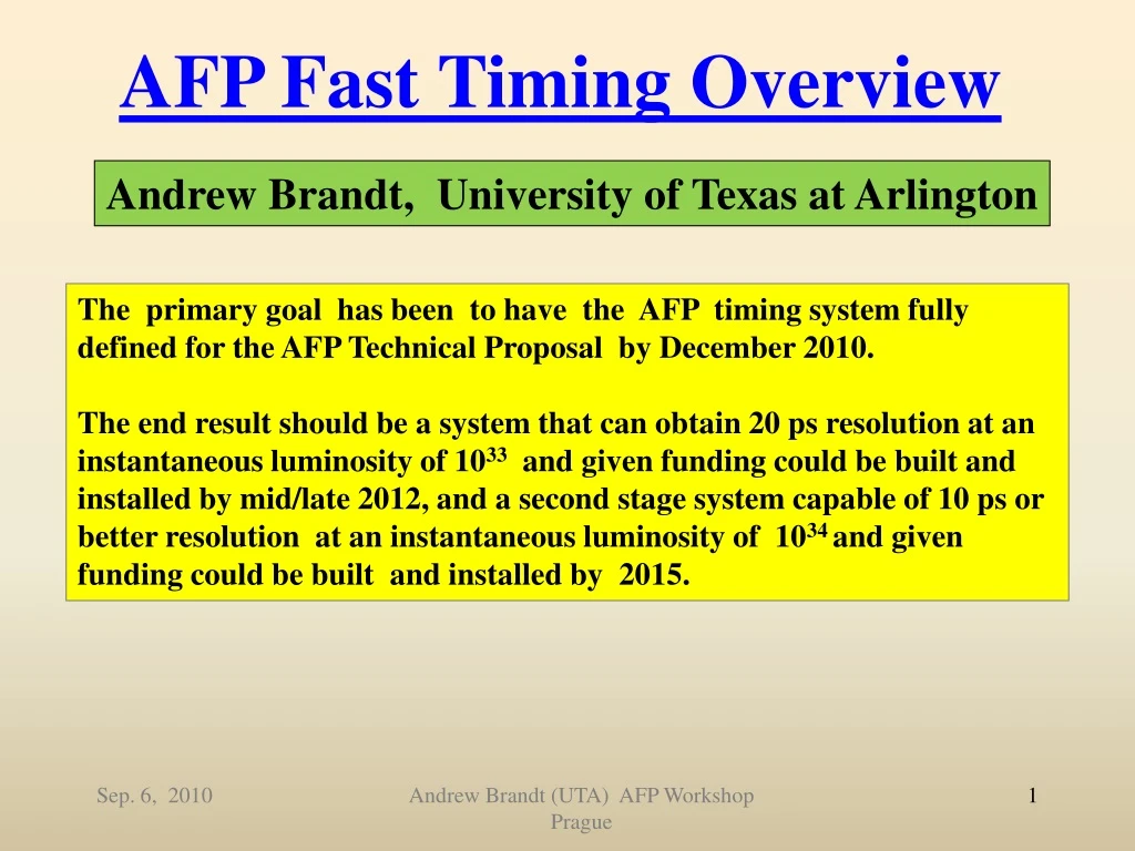
AFP Fast Timing Overview. Andrew Brandt, University of Texas at Arlington. The primary goal has been to have the AFP timing system fully defined for the AFP Technical Proposal by December 2010.

E N D
AFP Fast Timing Overview Andrew Brandt, University of Texas at Arlington The primary goal has been to have the AFP timing system fully defined for the AFP Technical Proposal by December 2010. The end result should be a system that can obtain 20 ps resolution at an instantaneous luminosity of 1033 and given funding could be built and installed by mid/late 2012, and a second stage system capable of 10 ps or better resolution at an instantaneous luminosity of 1034 and given funding could be built and installed by 2015. Andrew Brandt (UTA) AFP Workshop Prague
Timing System Requirements • 10 ps or better resolution • Acceptance over full range of proton x+y • Near 100% efficiency • High rate capability • Segmented : for multi-proton timing and L1 trigger • Robust: capable of operating with little or no intervention in radiation environment (tunnel) - PMT’s, detectors, cables, and electronics must be able to tolerate radiation levels (for PMT’s this includes tolerance to external radiation damage, as well as to internal photocathode damage) - Backgrounds from other particles must not impair operation Andrew Brandt (UTA) AFP Workshop Prague
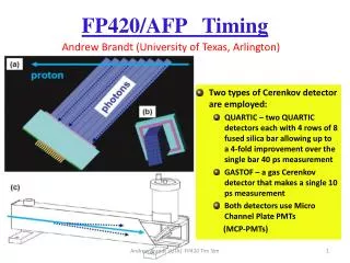
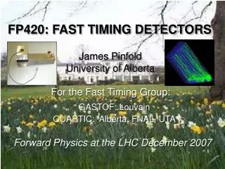
FP420 Baseline Plan 2 QUARTICs 1 GASTOF Lots of 3D silicon • Two types of Cerenkov detector are employed: • GASTOF – a gas Cerenkov detector that makes a single precise measurement • QUARTIC – two QUARTIC detectors each with 4 rows of 8 fused silica bar allowing up to a 4-fold improvement over the single bar resolution • Both detectors use Micro Channel Plate PMTs (MCP-PMTs) Andrew Brandt (UTA) AFP Workshop Prague
QUARTIC is Primary AFP Timing Detector proton UTA, Alberta, Giessen, Stonybrook (w/help from Louvain and FNAL) photons 4x8 array of 5x5 mm2 fused silica bars Only need a 40 ps measurement if you can do it 16 times: 2 detectors with 8 bars each, with about 10 pe’s per bar • Multiple measurements with “modest” resolution simplifies requirements in all phases of system • 1) We have a readout solution for this option • We can have a several meter cable run to a lower radiation area where electronics will be located • Segmentation is natural for this detector • Possible optimization with fibers instead of bars—discuss later
Micro-Channel Plate Photomultiplier Tube Burle/Photonis 64 channel 10 or 25 m pore has been tested extensively with test beam and laser and would be default for first stage except for lifetime issues Andrew Brandt (UTA) AFP Workshop Prague
MCP-PMT Requirements Excellent time resolution: 20-30 ps or better for 10 pe’s High rate capability: Imax= 3 A/cm2 Long Lifetime: Q= 30 C/cm2/year at 400 nm Multi anode: pixel size of ~6 mm x 6mm Pore Size: In our experience need 10 m or better Tube Size: 40 mm round, 1 or 2 inch square Need to have capability of measurements in different parts of tube between 0-2 ns apart, and in same part of the tube 25 ns apart Photek 240 (1ch) Hamamatsu SL10 (4x4) Andrew Brandt (UTA) AFP Workshop Prague
QUARTIC Timing 2008 CERN TB Dt Npe=(area/rms)2 56.6/1.4=40 ps/bar using Burle 64 channel 10 m pore tube including CFD! Time difference between two 9 cm quartz bars after Louvain constant fraction implies a single bar resolution of 40 ps for about 10 pe’s (expected 10 pe’s from simulations). Need to demonstrate N (more later)
QUARTIC Efficiency CERN TB (a) (b) All tracks (Bonn Silicon Telescope) Tracks with a Quartz bar on Events Shape due to veto counter with 15mm diameter hole 6mm Use tracking (b)/(a) to determine that QUARTIC bar efficiency is high and uniform (c) Efficiency 6 mm Andrew Brandt (UTA) AFP Workshop Prague Strip #
(a) UTA Laser System Beam Mode Fiber Mode (c) (b) (d) Andrew Brandt (UTA) AFP Workshop Prague
Time Resolution from Laser Tests Andrew Brandt (UTA) AFP Workshop Prague Laser tests of 10 µm tube show that with sufficient amplification there is no dependence of timing on gain (low gain operation extends lifetime of tube)
Saturation from Laser Tests Saturation independent of number of pixels hit, with proposed glass can obtain required rate Andrew Brandt (UTA) AFP Workshop Prague
Electronics Layout Andrew Brandt (UTA) AFP Workshop Prague
Alberta has created modified version (ALCFD) with LVPECL output to operate w/HPTDC board LCFD ZX60 4 GHz amplifier (we use pairs of amps in different combinations to control total amplification) • LCFD (Louvain Constant • Fraction Discriminator) • 12 channel NIM unit • mini-module approach • tuned to PMT rise time • Excellent performance : <10 ps resolution for 4 or more pe’s • <5 ps for 10 pe’s Remote control for threshold Andrew Brandt (UTA) AFP Workshop Prague
Alberta HPTDC board Jim Pinfold Shengli Liu 12 ps resolution with pulser including non-linearity corrections. Successfully tested at UTA laser test stand with laser/10 m tube/ZX60 amp/ALCFD (and in TB) 14 ps resolution in laser tests Andrew Brandt (UTA) AFP Workshop Prague
Reference Timing Reference timing is needed to connect two arms ~1km apart; what we want is TL-TR, what we measure is (TL-Tref)-(TR-Tref), so need small jitter in Tref This setup has just been tested to give <10 ps (over 20 C range) with 1000 ft cable The reference system uses a phase lock loop to maintain a constant number of wavelengths in a 100m cable. This synchronizes the phase of the RF at each end of the cable. A voltage controlled oscillator (VCO) launches a signal down the cable where it is reflected and sent back. The returned signal is then interfered with an external RF reference to synchronize it with the reference. At the end of the 100m cable the signal is sampled with a directional coupler which mixes the signal to produce a DC level. That DC level is fed back to the VCO to maintain a constant number of wavelengths in the cable. Andrew Brandt (UTA) AFP Workshop Prague
Lifetime Issues Lifetime due to positive ions damaging the photocathode is believed to be proportional to extracted charge: Q/year = I*107 sec/year Q for 3 A/cm2 is 30 C/cm2/yr Can reduce this requirement with fiber detector but still off by at least a factor of 20, so developed an R&D plan to pursue this Andrew Brandt (UTA) AFP Workshop Prague
Options for Improved Lifetime MCP-PMT No Funding (yet)! Pursuing funds to commission, purchase, and test longer lifetime tubes. Photek will build tubes to our specification, Photonis will insert Arradiance modified MCP into their tubes. Ion barrier, already demonstrated, this promises a factor 5 to 6 lifetime improvement (at the cost of a 40% collection efficiency reduction) Electron scrubbing, already demonstrated internally by Photonis, promises a factor 5 to 10 lifetime improvement Z-stack, already demonstrated, this promises a factor of 10 lifetime improvement (A.Yu. Barnyakov, et al., Nucl. Instr. and Meth. A 598 (2009) 160) Arradiance coated MCP’s, to be demonstrated, this promises a factor of 10 or more lifetime improvement Various combinations of these factors are possible and should give multiplicative improvement factors, except for the electron scrubbing and Arradiance coating, which would be expected to be orthogonal Andrew Brandt (UTA) AFP Workshop Prague
Possible Showstoppers for TP • PMT Lifetime. I have developed a detailed plan to address • this issue and believe the problem is solvable with funding and • cooperation from PMT vendors. NO funding, so no solution. • Will not have a solution within the next couple years at this point. • Nagoya’s SL10 4x4 with ion barrier between MCP’s is best existing • option and might work for 1033 phase (not tested by us yet). • Background from halo protons interacting in beampipe • and contaminating timing measurement. This urgently needs • attention and no one is working on it!!! • 3) Radiation damage to electronics (needs manpower) • 4) Latency (needs studies from LAr) Andrew Brandt (UTA) AFP Workshop Prague
Issues for Technical Proposal 1) Detector optimization: a) quartz fibers (Giessen, Alberta): this would allow finer binning near the beam where rate is highest. Instead of four 6 mm bins, propose 1.5, 3, 6, 12. Would need to defuse light from smaller bin and focus light from larger bin to fit into same size pixel. b) Need design with no cracks between rows c) Need to test filtering of high wavelengths for use with solar blind photocathode. 2) QUARTIC Electronics - rad hard amplifier - PMT to amplifier cables, amplifier board - Location of CFD’s - Location of HPTDC boards - 80 MHz or 160 MHz HPTDC? high res HPTDC? - NINO chip - interface to ROD Andrew Brandt (UTA) AFP Workshop Prague
Issues for Technical Proposal 3) GASTOF Electronics (?) -default is to plug into QUARTIC chain (degrades resolution) -sampling chip? -rad hardness? -multi-anode design? 4) Reference Timing (Jeff Gronberg LLNL +SLAC, +UTA EE?) -optimizing clock/cable -interface electronics -temperature control of cable 5) L1 Trigger -provided by LCFD coincidence (Alberta+?) 6) Cabling of full chain (?) 7) LV/HV (?) Andrew Brandt (UTA) AFP Workshop Prague
Aug 23-30 CERN Test Beam ANALYSIS IN PROGRESS QUARTIC: • New quartz bar prototype test (Alberta 8 long-bar prototype), use scope to measure raw signal and compare to laser, pulse height, number of pe’s, timing resolution • 8 channel electronics test AMP->CFD->HPTDC • [sqrt(N) test] study coherent noise effects and 8-channel timing • compare 25 um and two 10 um Burle tubes (single channel and also 8 channel) • Color dispersion tests with long bar and filter (need to borrow photek tube for this)[not done] GASTOF: • Resolution for Hamamatsu type Gastof [no Photek tubes available] FIBER: • Giessen fiber detector with Giessen readout • Repeat for QUARTIC readout • Alberta fiber bundle comparison tests Andrew Brandt UTA Test Beam Planning
Alberta Electronics Plan • Alberta has copied and upgraded Louvain CDF and developed HPTDC board • Goals: -Complete design of a 3 HPTDC chip, 8 channel HPTDC board based on successful one chip design (due to occupancy issues only 4 channels available per chip, and one of those is used for reference timing, so a 3 chip board gives 8+1 channels) -Documentation and further system tests, including connections with ROD • Manpower:- Jim Pinfold- Shengli Liu (main Electrical Engineer) Andrew Brandt UTA
Stony Brook Electronics Plan Goals: - Tests of chain PULSER==>Preamp==>CFD- SPICE model of the chain PreAmp==>CFD==>Trigger- test of trigger circuitry- detailed design of PreAmp PCB- detailed design of Trigger circuitry Manpower:- Michael Rijssenbeek - Dean Schamberger: Design/consultations/supervision - Jack Steffens - Senior Tech: PCB and jigs- Taklam Li (Physics undergrad) - Fall- 1-2 REU students - Summer. Andrew Brandt UTA
UTA Laser Plan • Goals: - Finish cross talk and multi-proton studies - 2nd 10 m tubes evaluation, - Borrow SL10?- Submit results of these and other laser studies over the past 1.5 years to J. Inst (this also includes detailed studies of timing of Burle 10 and 25 m tubes, Saturation/Rates, Photek tube - Lifetime tests? -Photek Tests? • Manpower:- Andrew Brandt- Ian Howley (Ph. D. student), Ryan Hall (was UG, entering UTA Ph. D. program) - Monica Hew, Keith Gray, James Bourbeau+… (UG) Andrew Brandt UTA
Conclusions • We have developed a fast timing system for AFP that seems to be capable of ~10 ps resolution, still some loose ends to address • Work in progress: • 1) final optimization of detector (quartz fibers could lower maximum rate by 2-3 by more sensible binning) • 2) developing final HPTDC board and trigger circuit • 3) test beam analysis and laser tests (including studies of multiple proton effects, lifetime) • 4) developing and testing long-life MCP-PMT (no funding) • 5) evaluating radiation tolerance of all components and upgrading as needed • 6) SiPm alternative (Rhonzhin, Albrow) • Plan to write-up results for Technical Proposal