Download
1 / 21
210 likes | 336 Vues
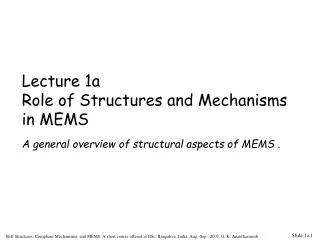
CS61CL – Machine Structures 10-22-08. David Culler Electrical Engineering and Computer Sciences University of California, Berkeley http://www.eecs.berkeley.edu/~culler. Outline. Looking back Linking lab Logic Gates: Q&A Technology Moore’s Law – Transistors everywhere …

E N D
CS61CL – Machine Structures10-22-08 David Culler Electrical Engineering and Computer Sciences University of California, Berkeley http://www.eecs.berkeley.edu/~culler
Outline • Looking back • Linking lab • Logic Gates: Q&A • Technology • Moore’s Law – Transistors everywhere … • The Digital Abstraction • Looking Ahead • Combination Logic, Synchronous Design Discipline, CAD CS61CL F08
Object file 20: SW $ra, 16($sp) 360 20: SW $ra, 16($sp) 0610 def “foo” int 20 … Linking Object file • Resolve names to addresses • Relocate code and data blocks • Adjust internally resolved addresses exe file Code J ____ 32: 60: J _32_ 80: LW _16_ 100 20 J ____ 132: Data 132 160: J _32_ 0610 16: 396 20 180: LW _16_ Symbol table ref “foo” ext 32 def “bar” int 32 ref “bar” int 60 ref “xyz” int 80 ddef “xyz” int 16 CS61CL F08
Questions CS61CL F08
Combinational Logic Symbols • Common combinational logic systems have standard symbols called logic gates • Buffer, NOT • AND, NAND • OR, NOR A Z A Easy to implementwith CMOS transistors(the switches we haveavailable and use most) Z B A Z B CS61CL F08
X Y Z0 0 10 1 11 0 1 1 1 0 X Y Z0 0 10 1 01 0 0 1 1 0 X Y Z0 0 00 1 11 0 1 1 1 0 X Y Z0 0 10 1 01 0 0 1 1 1 more Boolean Expressions to Logic Gates • NAND • NOR • XOR X Y • XNOR X = Y X Z Y X Z Y X xor Y = X Y' + X' YX or Y but not both ("inequality", "difference") X Z Y X xnor Y = X Y + X' Y'X and Y are the same ("equality", "coincidence") X Z Y CS61CL F08
Relationship Among Representations • Theorem: Any Boolean function that can be expressed as a truth table can be written as an expression in Boolean Algebra using AND, OR, NOT. How do we convert from one to the other? CS61CL F08
Moore’s Law – 2x stuff per 1-2 yr CS61CL F08
Example: Intel Pentium CS61CL F08
Primarily Crystalline Silicon 1mm - 25mm on a side 100 - 200M transistors (25 - 50M “logic gates") 3 - 10 conductive layers 2002 - feature size ~ 0.13um = 0.13 x 10⁻⁶ m “CMOS” most common - complementary metal oxide semiconductor Chip in Package Integrated Circuits • Package provides: • spreading of chip-level signal paths to board-level • heat dissipation. • Ceramic or plastic with gold wires. CS61CL F08
Integrated Circuits • Uses for digital IC technology today: • standard microprocessors • used in desktop PCs, and embedded applications • simple system design (mostly software development) • memory chips (DRAM, SRAM) • application specific ICs (ASICs) • custom designed to match particular application • can be optimized for low-power, low-cost, high-performance • high-design cost / relatively low manufacturing cost • field programmable logic devices (FPGAs, CPLDs) • customized to particular application after fabrication • short time to market • relatively high part cost • standardized low-density components • still manufactured for compatibility with older system designs CS61CL F08
The Digital Abstraction • Logical 1 (true) : V > Vdd –V th • Logical 0 (false) : V < Vth • Logical Gates • behave like boolean operators on these voltage signals • Produce signals that can be treated as logical values +3 Logic 1 V Logic Gate Logic 0 0 CS61CL F08
in out T F F T Example: NOT +3 Logic 0Input Voltage not( out, in) Vout Logic 1Input Voltage 0 +3 Vin CS61CL F08
Switches: basic element of physical implementations • Implementing a simple circuit (arrow shows action if wire changes to “1”): A Z close switch (if A is “1” or asserted)and turn on light bulb (Z) Z A open switch (if A is “0” or unasserted)and turn off light bulb (Z) Z A CS61CL F08
CMOS “Devices” • MOSFET (Metal Oxide Semiconductor Field Effect Transistor) • Essentially a voltage-controlled switch • N: closed when gate is Hi • P: closed when gate is Lo Top View Cross Section nFET pFET CS61CL F08
Transistor-level Logic Circuits (inv) • Inverter (NOT gate): Vdd Gnd what is the relationship between in and out? Vdd in out 3 volts 0 volts Gnd 0 volts 3 volts CS61CL F08
Big idea: Self-restoring logic • CMOS logic gates are self-restoring • Even if the inputs are imperfect, switching time is fast and outputs go “rail to rail” • Doesn’t matter how many you cascade • Although propagation delay increases • Limit fan-out to ensure sharp and complete transition CS61CL F08
Element of Time • Logical change is not instantaneous • Broader digital design methodology has to make it appears as such • Clocking, delay estimation, glitch avoidance +3 Propagation delay Vout 0 T CS61CL F08
clock distributed to all flip-flops ALL CYCLES GO THROUGH A REG! Combinational Logic Blocks (CL) Acyclic no internal state (no feedback) output only a function of inputs Registers (reg) collections of flip-flops Synchronous Circuit Design CS61CL F08
Modern Hardware Design • Extremely Software Intensive • Design tools (schematic capture, hardware description lang.) • Simulation tools • Optimization tools • Verification tools • Supply chain and project management • Managing complexity of fundamental • Modularity • Methodology • Clarity • Technology independence • Push the edge • Of the available tools • Of the technology CS61CL F08
Basic Design Tradeoffs • You can usually improve on one at the expense of one or both of the others. • These tradeoffs exist at every level in the system design - every sub-piece and component. • Design Specification - • Functional Description. • Performance, cost, power constraints. • As a designer you must make the tradeoffs necessary to achieve the function within the constraints. CS61CL F08