Download
1 / 64

E N D
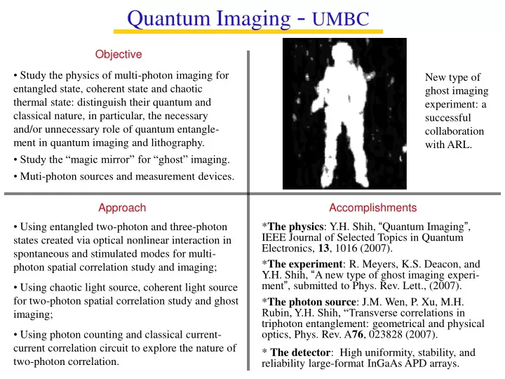
Quantum Imaging -UMBC Objective • Study the physics of multi-photon imaging for entangled state, coherent state and chaotic thermal state: distinguish their quantum and classical nature, in particular, the necessary and/or unnecessary role of quantum entangle-ment in quantum imaging and lithography. • Study the “magic mirror” for “ghost” imaging. • Muti-photon sources and measurement devices. New type of ghost imaging experiment: a successful collaboration with ARL. Approach Accomplishments • Using entangled two-photon and three-photon states created via optical nonlinear interaction in spontaneous and stimulated modes for multi-photon spatial correlation study and imaging; • Using chaotic light source, coherent light source for two-photon spatial correlation study and ghost imaging; • Using photon counting and classical current-current correlation circuit to explore the nature of two-photon correlation. *The physics: Y.H. Shih, “Quantum Imaging”, IEEE Journal of Selected Topics in Quantum Electronics, 13, 1016 (2007). *The experiment: R. Meyers, K.S. Deacon, and Y.H. Shih, “A new type of ghost imaging experi-ment”, submitted to Phys. Rev. Lett., (2007). *The photon source: J.M. Wen, P. Xu, M.H. Rubin, Y.H. Shih, “Transverse correlations in triphoton entanglement: geometrical and physical optics, Phys. Rev. A76, 023828 (2007). * The detector: High uniformity, stability, and reliability large-format InGaAs APD arrays.
Part I:The Physics of Quantum Imaging Objective: “Study the physics of multi-photon imaging, distinguish their quantum and classical nature, in parti-cular, the necessary and/or unnecessary role of quantum entanglement in quantum imaging.”
Quantum imaging has demonstrated two peculiar features: Enhancing the spatial resolution beyond diffraction limit; (2) Reproducing “ghost” images in a “nonlocal” manner. Either the nonlocal behavior observed in ghost imaging or the apparent violation of the uncertainty principle explored in the quantum lithography are due to the coherent superposition of two-photon amplitudes, a nonclassical entity corresponding to different yet indistinguishable alternative ways of triggering a joint-detection event.
Classical Imaging - the concepts
Idealized Classical Imaging Gaussian thin lens equation Point-point relationship between theobject-planeand theimage-plane is the result of constructive interference of the fields.
Diffraction-limited Classical Imaging Gaussian thin lens equation somb(x) = 2J1(x) / x Point-“spot” relationship between theobject planeand theimage plane is the result of constructive superposition: a diffraction pattern.
Biphoton “ghost” Imaging So Si “Ghost” Image: an EPR Experiment in momentum and position correlation. PRA, 52, R3429 (1995); PRL, 74, 3600 (1995).
What is so special about entangled two-photon state? “Can quantum mechanical physical reality be considered complete?” Einstein, Poldosky, Rosen, Phys. Rev. 47, 777 (1935). Proposed the entangled two-particle state according to the principle of quantum superposition: Although:
What is so special about entangled two-photon states? A typical EPR state: In EPR’s language, the signal and the idler may come out from any point of the object plane; however, if the signal (idler) is found in a certain position, the idler (signal) must be found in the same position, with 100% certainty.
Biphoton “ghost” Imaging & Photon #1 stop at a point on object plane Photon #2 stop at a unique point on image plane Result of a constructive superposition of two-photon amplitudes, a nonclassical entity corresponding to different yet indistinguishable alternative ways of triggering a joint-detection event.
Lens-less ghost Imaging X2 D2 Thermal light (Near-field) D1 C.C X2 S.C S.C X2 X2
Near-field Ghost Image with chaotic light Thermal light source Correlator Photon Counting Correlation Measurement
Recent Experiment In collaboration with ARL Ghost image of an Army soldier A photon counting detector, D1, is used to collect and to count all the photons that are randomly scattered-reflected from the soldier. A CCD array (2D) was facing the light source instead of the object. An image of the soldier was observed in the joint-detection of D1 and the CCD.
Chaotic light Ghost Imaging Constant Background Image
Source D2 D1 Superposition of two-photon amplitudes
Superposition of classical fields? Does it make any sense in Maxwell theory of light?
Imaging x-x Position-Position Correlation HBT andGhost Imaging k-k Momentum-Momentum Correlation
HBT Thermal light ghost imaging Far-field 1956 Near-field 2006 50 years We cannot but stop to ask: What has been preventing this simple move for 50 years (1956-2006)? Something must be terribly misleading to give us such misled confidence not to even try the near-field measurement in half a century.
k1 Mode 1 Far-field (Fourier transform Plane) Mode 2 k2 Identical modes: Different modes: The HBT experiment was successfully interpreted as statistical correlation of intensity fluctuations. In HBT, the measurement is in far-field (Fourier transform plane). The measured two intensities have the same fluctuations while the two photodetectors receive the same mode and thus yield maximum correlation. When the two photodetector receive different modes, however, the intensities have different fluctuations, and thus no correlation is observable.
Statistical correlation of intensity fluctuation ??? It does not work for near field !!! Identical modes: Different modes: Near-field
The physics of chaotic light ghost imaging? “Can Two-photon Correlation of Chaotic Light Be Considered as Correlation of Intensity Fluctuations?” PRL, 96, 063602 (2006) (G. Scarcelli,V. Berardi, and Y.H. Shih). “A New Type of Ghost Imaging Experiment”, submitted to Phys. Rev. Lett., (2007) (R. Meyers, K.S. Deacon, and Y.H. Shih). “Quantum Imaging”, IEEE J. of Selected Topic in Quantum Electronics, 13, 1016 (2007) (Y.H. Shih).
The Physics * The nonlocal behavior observed in biphoton ghost imaging is due to the superposition of two-photon amplitudes, a nonclassical entity corresponding to different yet indistinguish-able alternative ways of triggering a joint-detection event. * The lens-less ghost imaging of thermal light is an interference phenomenon involving the superposition indistinguishable two-photon alternatives, rather than statistical correlation of intensity fluctuation. Ghost imaging: a quantum phenomenon of light. *
Lensless imaging with a classical statistical source Klyshko Picture
The current-current correlation is given by where This are derived using
All the rays from the point at A coherently add at in the region centered at B . One can say the same thing in terms of the wave vectors.
If we change the detection scheme, we get a different result. In the paraxial approximation: Now each point of the detector A acts like the source of a spherical wave that illuminates the entire object; consequently,
for dA=dB We see that although the two results are the same for completely incoherent sources, they differ in the more realistic case. When looked at in the Klyshko picture, allowing for the phase conjugate nature of the source, the last case looks like coherent imaging, while the previous case looks like incoherent imaging.
. . . . . . IR LASER TRANSMITTER AND RECEIVER . . Range Finder, Stand Off Detection, and 3-D Lidar (APD Arrays) Applications DIfferential SCattering/DIfferential Absorption Lidar (DISC/DIAL)
High Performance Photon Counting Detectors and Arrays Space Optical Communications Quantum Communication & Image Applications
Potential issues with mesa APDS for space applications: Short lifetime from early breakdown (reliability) Dark current increases over time (stability) Mesa vs. Guard-Ring Mesa Guard-Ring
Reliability of Guard-Ring APDS Aging test condition: 200oC/I=100A Testing method: measure dark current at M~10 periodically * S. Tanaka et al on OFC 2003
1. Low Dark Counts: Dark current is caused by surface leakage, tunneling, defects assisted tunneling. Can be reduced by decrease the electrical field in the active (absorption) region. 2. High Gain and High Differential Gain High gain can be obtained with high bias voltage. However, with high bias, a high dark current will also be produced. High differential gain relies on high rising slope of APD (dG/dV). An ideal PC APD will have a straight angle I-V curve, which can be achieved with better device designs. 3. Designing and Fabricating Materials with Reduced After-Pulse Dark Current (AFDC) Amplitude and Duration AFDC comes from traps in the avalanche regions and trapped carriers in the hetero-interface. Interstitial Zn atoms created during the diffusion processes are source of traps and can be activated and converted to substitutional dopants by appropriate annealing procedures. More steps of InGaAsP quaternary layers (1.1Q, 1.2Q, 1.3Q, 1.5Q, ..etc.) can added to the InP/InGaAs interface to reduce hole trapping. Key Issues for Photon Counting (PC)
+Vop I Iop Vout VB V Vop Geiger Mode Operations-I • Passive Quenching – Biased above breakdown voltage ( Vop-Vb< ~2V), rely on a series resistance to reduce voltage drop on the APD when avalanche is taking place. Advantages: simple circuits, disadvantages: long recovery time.
+Vop I Control Voltage supplier Iop Avalanche Sensing And trigger circuits VB Vout V Vop Geiger Mode Operations-II 2. Active Quenching – Normally biased above breakdown voltage ( Vop-Vb< ~2V). Once sensed that an avalanche process is taking place, immediately reduce the bias below Vb. Advantages: relatively short recovery time (still limited by afterpulse dark counts). Disadvantages: more complex circuits.
+Vop Vout Geiger Mode Operations-III 3. Gated Operations – Normally biased below or around Vb. A short electrical pulse is applied to the APD terminal to raise the bias voltage above Vb and gain when photons are coming. Advantages : simpler ckt and very high gain. Disadvantages: can only work with periodic signals and synchronization is an issue. I Vac Idc VB V Vdc
Vp VB Optimize Design To Achieve High Differential Gain and Low Dark Current Reducing the distance between the punch through voltage and the breakdown voltage will help to reduce the voltage drop falling on the small bandgap absorption region
Dark Current I-V Characteristics Changing with Temperature * The dark current is reduced • The gain is increased • A sharp rising gain with the bias voltage will help to choose good operating points.