Download
1 / 16
190 likes | 560 Vues
Programming the ATmega16. B. Furman 14SEP2010. Power Source. Signal Conditioning. Power Interface. User Interface. Actuator. Sensor. System to Control. ME 110 ME 136 ME 154 ME 157. ME 182 ME 189 ME 195. Mechatronics Concept Map. ME 106 ME 120. Controller (Hardware & Software).

E N D
Programming the ATmega16 B. Furman 14SEP2010
PowerSource SignalConditioning PowerInterface UserInterface Actuator Sensor System toControl ME 110 ME 136 ME 154 ME 157 ME 182 ME 189 ME 195 Mechatronics Concept Map ME 106 ME 120 Controller(Hardware & Software) ME 106 ME 190 ME 187 ME 106 ME 106 ME 120 ME 106 ME 154 ME 157 ME 195 ME 120 ME 297A BJ Furman 26JAN06
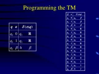
7 6 5 4 3 2 1 0 Recap Last Lecture Audience participation required! • Binary and hex numbers • Digital pins as inputs or outputs • Pins are bidirectional for digital I/O • DDRx (x=A, B, C, or D) register determines direction • 8-bit register • a ‘1’ means • a ‘0’ means • main_RC.c • Programmer’s block • #include • Initialization function, init(); • DDRA, DDRB, and uart_init()
Test Your Comprehension • Write a statement that will make all pins of PORTC to be outputs • DDRC = • DDRC = 0b11111111; • DDRC = 255; • Write a statement that will make pins 5, 3, and 1 of PORTC to be outputs, and the rest inputs • DDRC = 0b00101010; 0xFF;
Structure of main() • Look again at main_RC.c • init() • printf_example() • Declaration of variables • char, string, uint8_t, uint16_t, uint32_t, double • printf() • format string • while(1) • Why? • PORTB = PINA; • Explain what is going on as a result of this statement
ATmega16 Port Pin Details • See the ATmega 16 data sheet, p. 50 - 67 • Port pins consist of three register(special memory location) bits: • DDRx • Data Direction bit in DDRx register (read/write) • PORTxn • PORTxn bit in PORTx data register (read/write) • PINxn • PINxn bit in PINx register (read only)
ATmega16 Internal Architecture http://www.atmel.com/dyn/resources/prod_documents/doc2466.pdf
ATmega16 Features http://www.atmel.com/dyn/resources/prod_documents/doc2467.pdf
Challenge: Make bits 5 and 3 of PORTB high and the rest low Bit Manipulations • Examples of how to work with Port pins • Setting bits • Clearing bits • Toggling bits
Summary of Bit Manipulation • Setting a bit (making it a ‘1’) • Bitwise OR the PORTx register with the corresponding bit mask • Ex. PORTB | = _BV(3); • Clearing a bit (making it a ‘0’) • Bitwise AND the PORTx register with the corresponding complemented bit mask • Ex. PORTB & = ~( _BV(3) ); • Toggling a bit (making it flip) • Bitwise XOR the PORTx register with the corresponding bit mask • Ex. PORTB ^ = _BV(3);
Pull-up Resistors • Pins configured as INPUTS can be ‘pulled up’ to VTG • Why is this useful? • Puts an input pin in a known state (logic high) if no external influence has pulled it down (to logic low) • Example of a switch connected between a pin and ground • How is it done? • When the pin is configured as an input, SET the corresponding bit in PORTxn • Undone by clearing the bit
Recap ATmega16 Digital I/O • Pins are bi-directional. Can configure as: • Inputs – _______ determines the pin voltage • Outputs – ______ determines the pin voltage • Direction determined by bits in DDRx register • Where x is A – D (and corresponds to all 8 pins associated with the port) • If configured as output: • Program can specify a pin to be high (VTG) or low (GND) by writing a corresponding 1 or 0 (respectively) to PORTx register • Ex. To make Port C pins 7, 3, and 4 low, and the rest high • PORTC=___________; (write in binary, then in hex)
VTG PA7 PA6 PA5 PA4 PA3 PA2 PA1 PA0 Recap ATmega16 Digital I/O, cont. • If pins configured as input, this means: • External device can pull pin voltage high or low • i.e. take up to VTG or take down to GND • You can determine the state of the portpins by reading the PINx register • Grabs all eight logic levels at the same time • Ex. PORTA configured as inputs unsigned char a_pins; a_pins=PINA; What is the content of a_pins: binary:__________ hex:_____
VTG PA7 PA6 PA5 PA4 PA3 PA2 PA1 PA0 Recap ATmega16 Digital I/O, cont. • If pins configured as input, cont.: • Can turn pull-up resistors on or off by writing a 1 or 0 to corresponding pins in PORTx • A pull-up resistor internally connects a pin to VTG to give it a defined state (logic high, i.e., 1) • Ex. Write the code that will: • Make Port A pins inputs • Turn on pull-up resistors • Read the voltages on the pins and store them in a variable, testA • What is the value of testA in binary and hex?
VTG PA7 PA6 PA5 PA4 PA3 PA2 PA1 PA0 Reading PORTA Pins Example unsigned char testA; DDRA=0; testA=PINA; What is the content of testA? binary: 11111001 hex: F9