Download
1 / 16
160 likes | 246 Vues
Class A Operating Mode. I out. Time. One device conducts for the whole of the a.c. cycle. Conduction angle = 360 °. Class A Output Stage. Transistors only conduct current in one direction.

E N D
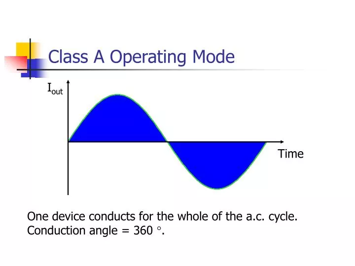
Class A Operating Mode Iout Time One device conducts for the whole of the a.c. cycle. Conduction angle = 360 °.
Class A Output Stage • Transistors only conduct current in one direction. • 360° conduction angle therefore requires a d.c. bias so that the collector current does not try to go negative. • Common circuit design is the Emitter Follower or Common Collector Amplifier.
Emitter Follower Basics • As long as the collector current is positive, VBE» 0.7 V. • VE, therefore equals VB – 0.7 V, i.e. unity voltage gain. • Input current will be approximately b times smaller than output current though – i.e. current gain.
Emitter Follower Analysis Quiescent Conditions
A.C. Response To relate vout to vin, must relate base voltage, vb to vin and vout to vb. vb
(I) – vout vs. vb vb ve
iRB iIN iB (II) - vin vs. vb Potential divider is formed between RS and rin.
Bias Current Two possible ways of approximating the 15 mA current source : Resistor Current Mirror
Resistor Biasing When the output voltage is at its lowest possible value, the output transistor has just turned off : i.e. maximum output signal has 7.5 V peak amplitude
Current Mirror Biasing Again, when the output transistor has just turned off :
Resistor vs. Current Mirror • Resistor biasing is simpler and cheaper than building a current mirror, however… • Maximum output swing is limited using a resistor. • The extra resistor appears in parallel with RL, thereby lowering rin. • Power dissipation is increased.
Microcap simulation #1 EEM3A-1.CIR
Summary • A class A output stage can be realised by an emitter follower circuit. • Voltage gain is approximately unity. • Current gain is high. • Ideally, a current mirror is required to bias the emitter follower.