Download
1 / 18
180 likes | 281 Vues
Generation of CDFGs from Scheduled and Pipelined Assembly Code. The 18th International Workshop on Languages and Compilers for Parallel Computing October 20, 2005 David Zaretsky, Gaurav Mittal, Robert Dick, and Prith Banerjee

E N D
Generation of CDFGs from Scheduled and Pipelined Assembly Code The 18th International Workshop on Languages and Compilers for Parallel Computing October 20, 2005 David Zaretsky, Gaurav Mittal, Robert Dick, and Prith Banerjee Department of Electrical Engineering and Computer Science, Northwestern University College of Engineering, University of Illinois at Chicago
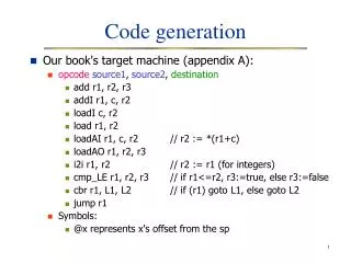
2500 DSP performance requirements for new communication technologies Future Broadband 2000 4G Wireless 1500 DSP Operations per second (Billion MAC/s) 3G Wireless / WCDMA 1000 Video over IP HDTV, MPEG4 500 Standard DSP Performance Roadmap Voice over IP 2004 2000 2001 2002 2003 The Future of DSP Applications • Recent advances in embedded communications and control systems are pushing the computational limits of DSP applications, driving the need for hardware/software co-design system.
Binary Translation • Problems with high-level synthesis • High-level application unavailable • Hardware compiler unavailable • Binary Translation • Grammar • Operation Latencies • Software Pipelining • Processor Architecture Limitations • Functional Units • Data Paths • Physical Registers • Memory Spilling • Control and Data Flow Graphs • Optimizations • Scheduling • Design decisions
DSP Design Environment FPGA designers unfamiliar with DSP concepts Assembly Binary FREEDOM ASIC / FPGA Design Environment VHDLVerilog DSP designers not versed in FPGA design Manually created RTL Models RTL Simulation Verified RTL Models Logic Synthesis Netlist of Primitives Place & Route FREEDOM: Bridging the Gap • FREEDOM compiler automates the task of hw/sw partitioning for software binaries. • FREEDOM is an acronym for:Fabrication of Reconfigurable Hardware Environments from DSP Optimized Machine Code
Related Work • Binary Decompilation & Translation • Cifuentes93/96/98 • Kruegel04 • Dehnert03 • Stitt02/03 • Dynamic Binary Optimizations • Bala00 • Gschwind00 • Ye00 • Levine03 • Control and Data Flow Analysis • Kastner02 • Decker03 • Amme00 • Cooper02
Presentation Overview • FREEDOM Compiler Infrastructure • Data Dependency Analysis • CDFG Generation from Scheduled Assembly Code • Experimental Results • Summary & Conclusions
The FREEDOM Compiler • Common entry point for multiple assembly languages. • Intermediate levels: • Machine Language Syntax Tree • Control & Data Flow Graph • Hardware Description Language • Architecture Description Language provides resource information for target FPGA architecture. • Output: RTL VHDL/Verilog and testbench.
Machine Language Abstract Syntax Tree (MST) • Generic language encapsulates most ISAs, including predicated and parallel instruction sets. • All MST instructions are three-operand, predicated instructions: [pred] op src1 src2 dst • Operand Types: Memory Address, Label, Register, Immediate. • Operator types: • Logical: AND, NAND, NEG, NOR, NOT, OR, XOR, SLL, SRL, etc. • Arithmetic: ADD, DIV, MULT, SUB • Branch: BEQ, BGEQ, BGT, BLEQ, BLT, BNEQ, GOTO, CALL • Comparison: CMPEQ, CMPNE, CMPLT, CMPLE, CMPGT, CMPGE • Assignment: LD, ST, MOVE, UNION • General: NOP
Data Dependency Analysis • MST instructions are assigned • A timestep T • An operation delay • Each instruction in a parallel set is incremented by:Tn = T + 0.01 * n • Each instructions in an expanded set is incremented by: Tm = Tn + 0.0001 * m • The write-back stage of an instruction is defined as: wb = timestep + delay TIMESTEP PC OP DELAY SRC1 SRC2 DST 1.0000 0X0020 MULT (2) $A4, 2, $A4 2.0000 0X0024 LD (5) *($A4), $A2 2.0100 0X0028 ADD (1) $A4, 4, $A2 3.0000 0X002c ADD (1) $A4, $A2, $A3
CDFG Generation from Scheduled Assembly Code 0x0000 VECTORSUM: ZERO A7 0x0004 LDW *A4++, A6 0x0008 || B LOOP 0x000C LDW *A4++, A6 0x0010 || B LOOP 0x0014 LDW *A4++, A6 0x0018 || B LOOP 0x001C LDW *A4++, A6 0x0020 || B LOOP 0x0024 LDW *A4++, A6 0x0028 || B LOOP 0x002C || SUB A1, 4, A1 0x0030 LOOP: ADD A6, A7, A7 0x0034 || [A1] LDW *A4++, A6 0x0038 || [A1] SUB A1, 1, A1 0x003C || [A1] B LOOP 0x0040 STW A7, *A5 0x0044 NOP 4 • Pipelined assembly code present difficulties in CDFG generation • Complex control flows • Varying data dependencies • CDFG generation in 3 steps: • Generate a Control Flow Graph • Linearize Pipelined Operations • Generate Data Flow Graph
Building a Control Flow Graph • Based on work by K. Cooper et al, “Building a Control-Flow Graph from Scheduled Assembly Code,” Dept. of Computer Science, Rice University. • Generates a CFG in O(n) time. • Requires 3 Stages: • Partition the code at labels into a set of basic blocks. • Add edges between CFG blocks to represent normal flow of control. • Iteratively propagate pipelined branch and counter information in a simulated control flow.
Event-Triggered Operations • Analogous to a read/write pipeline architecture. • Event trigger and execution stages are offset by operation delay (d). • Implemented using a virtual shift register of size d. • Event is triggered by assigning a ‘1’ to the highest bit (d-1). • SRL operation is performed on the register in successive cycles. • Event is executed after d cycles, when a ‘1’ appears in the zero bit.
Linearizing Pipelined Branch Operations • Iteratively propagate pipelined branch and counter information in a simulated control flow. • Trigger a change in control flow after a number of delay cycles. • Only the event is propagated using the SRL operation. • Copy of branch instruction inserted at each execution point. • The branch is predicated on the event shift-register. • Intersecting branch paths are merged by OR-ing predicates. • The original branch instructions are replaced with NOPs.
Linearizing Pipelined Computational Operations • Multi-cycle instructions are serialized into well-defined data flow paths along the pipeline. • For an instruction with n delay slots, the value is propagated through virtual registers Rn-1Rn, Rn-2Rn-1, … R0R1, where R0 is the original register name. • Each instruction in the sequence is guarded by a predicate on an event-triggering register bit. • Intersecting data paths are merged by OR-ing predicates.
Building the Data Flow Graph • DFG represents data dependencies in each MST procedure. • DFG is generated using write-back times of MST instructions. DOTPROD: MVK .S1 500,A1 ZERO .L1 A7 MVK .S1 2000,A3 LOOP: LDW .D1 *A4++,A2 LDW .D1 *A3++,A5 NOP 4 MPY .M1 A2,A5,A6 SUB .S1 A1,1,A1 ADD .L1 A6,A7,A7 [A1] B .S2 LOOP NOP 5 STW .D1 A7,*A3
CDFG Optimizations • Traditional Optimizations • SSA • Common Sub-Expression • Copy Propagation • Constant Propagation • Constant Folding • Strength Reduction • Dead Code Elimination • Loop Unrolling • Register Allocation • Custom Optimizations • Identify I/O Ports • Undefined Var Elimination • Const Predicate Elimination • Memory Forwarding • Boolean Reduction • Shift Reduction • Block-Set Merging • Empty Block Extraction
Experimental Results • Each benchmark verified bit-true accurate using Modelsim. • ~9 instructions were added for each pipelined operation. • ~27% increase in code size during the linearization process. • Values reflect the size of the design before CDFG optimizations.
Summary & Conclusions • HLS compilers generally convert designs into CDFGs. • Optimizations • Scheduling • Design decisions • Generating CDFGs from pipelined and scheduled assembly code is complex. • FREEDOM compiler generates CDFGs in three stages: • Generate the control flow graph • Linearize the assembly code • Generate the data flow graph • Verification on highly pipelined benchmarks show improved performance.