Download
1 / 124
1.24k likes | 1.48k Vues
Preliminary Airworthiness Design Review for FIFI LS (Field-Imaging Far-Infrared Line Spectrometer) MPE 15 December 1998. Overview Albrecht Poglitsch MPE 15 December 1998. The FIFI LS Team. MPE Garching PI: Albrecht Poglitsch CoIs: Norbert Geis (Instrument Scientist)

E N D
Preliminary Airworthiness Design Review for FIFI LS (Field-Imaging Far-Infrared Line Spectrometer) MPE 15 December 1998
Overview Albrecht Poglitsch MPE 15 December 1998
The FIFI LS Team MPE Garching • PI: Albrecht Poglitsch • CoIs: Norbert Geis (Instrument Scientist) Reinhard Genzel (MPE director) Leslie Looney (Project Scientist) Dieter Lutz Linda Tacconi • Engineers: H. Dohnalek (Design engineer, cryo/mechanics) G. Kettenring (Support engineer, FE modeling) J. Niekerke (Electrical Engineer, control electronics) G. Pfaller (Head of MPE machine shop) M. Rumitz (Electrical engineer, readout electronics) H. Wang (Electrical engineer, control SW/HW) • Students: Dirk Rosenthal (Detector development) Walfried Raab (Cryostat definition, grating, optics) Alexander Urban (Detector & readout testing)
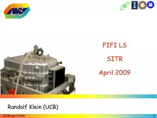
The FIFI LS Team (cont.) Univ. of Jena • CoI: Thomas Henning • Student: Randolf Klein (Software: user interface, data analysis)
FIFI LS Overview • PI Instrument for SOFIA • Wavelength ranges 42-110 mm & 110-210 mm • Resolution 0.03-0.1 mm (~ 175 km/s) • Instantaneous spectral coverage 1300 - 3000 km/s • Two 25´16 Ge:Ga photoconductor arrays • 5´5 (spatial pixels) ´ 16 (spectral channels) • Built by MPE Garching / Univ. Jena, Germany
Instrument • Cryostats and vacuum vessel built from Aluminum 5083 (AlMg4.5Mn) (TBD for vacuum vessel) • Indium sealed stainless steel necks • Work surfaces attached to bottom of cryostats • Work surfaces are not part of cryostats • Work surfaces connected via fiberglass tabs • Optic components mounted on work surface and surrounded by sheet aluminum cryogenic shields
Schedule Norbert Geis MPE 15 December 1998
Functional Hazard Analysis I Alexander Urban MPE 15 December 1998
Analysis Overview I.Cryogenic Issues 1.Quiescent cryogen boil-off • Cabin oxygen goes from 21% to 20.7% 2.Rapid cryogen boil-off, worst case • Cabin oxygen goes from 21% to 19.5% 3.Vacuum vessel overpressure • Use room temperature pressure relief devices 4.Cryogen can overpressure • Use double neck design with warm pressure relief devices
Analysis Overview II.Structural Issues 5.Estimated Masses • Total weight including cart: 595 kg • Total weight w/o cart: 490 kg 6.g-loading 7.Containment analysis 8.Structural analysis • Finite Element analysis will be performed 9. Lasersand Gases • Possible use of class IIIb or less alignment laser • No noxious gases used in FIFI LS
Cryogen Boil-off 1.Quiescent Cryogenic Boil-Off Assumptions • Cabin volume ~866 m3 (30000 ft3) • Must have O2³ 19.5% of cabin air • 8 hours flight Gas generation rate • 1l LHe produces 0.7 m3 gaseous He at room T, P • 1l LN2 produces 0.65 m3 gaseous N2 at room T, P • 36l LHe (main LHe cryostat) estimated hold time 75 h => 0.48l/h • 2.8l LHeII (HeII cryostat) pumping time 18 h => 0.15 l/h • 30l LN2 estimated hold time 29 h => 1.03 l/h
Cryogen Boil-off • For 8 hour flight, total boil-off is: • (0.48 l/h)(8h) = 3.8l LHe => 2.7 m3 gaseous He • (0.15 l/h)(8h) = 1.2l LHeII => 0.8 m3 gaseous He • (1.03 l/h)(8h) = 8.2l LN2 => 5.3 m3 gaseous N2 • Corrected for reduced pressure in cabin (~4/3 V0) • 4.7 m3 He and 7.0 m3 N2 • Impact on cabin oxygen is: • 21% (1 - 11.7/866) = 20.7% • This is above the minimum of 19.5% and assumes no ongoing recirculation
Cryogen Boil-off 2.Rapid Cryogen Boil-Off After Loss of Vacuum Assumption • 39l LHe and 30l LN2 boil-off instantly Gas generation rate • 39l LHe produces 27.3 m3 gaseous He at room T, P • 30l LN2 produces 19.5 m3 gaseous N2 at room T, P • Corrected for reduced pressure in cabin (~4/3 V0) • 36.4 m3 He and 26 m3 N2 Effect on cabin O2: • 21% (1 - 62.4/866) = 19.5% • This fulfills the requirement of 19.5% and assumes no ongoing recirculation
Vacuum Vessel Overpressure 3.Vacuum Vessel Overpressure • Vacuum vessel is not strong enough to contain all cryogen at room temperature • Warm pressure relief devices on vacuum vessel • Commercial spring-loaded relief device • Opens at 0.1 bar (TBD) differential pressure
Cryogen Vessel Overpressure 4.Cryogen Vessel Overpressure • None of the cryogen vessels are strong enough to contain all cryogen at room temperature LN2 Vessel • Two independent necks • Bleed valve at one neck • Two warm pressure relief devices at other neck opens at 0.1 bar (TBD) and 0.5 (TBD) differential pressure • No need for cold pressure relief device or double neck insert Main LHe Vessel and Auxiliary LHe Vessel • Use of double neck inserts
Double Neck Inserts • Two independent tubes to LHe cryostats • Total diameter of tubes: • Main LHe Cryostat: 2.6 cm • Auxiliary LHe Cryostat: 1.6 cm • One way valves are at room temperature • Insert removed during LHe transfer (on ground) • Red tag procedure guarantees installation of double neck inserts before flight • During pumping on LHe: • Additional warm pressure relief device in pump line if necessary
Double Neck Insert He Boil-Off • Maximum boil-off in case of vacuum failure • Assume: • Heat input of 1W per cm2 of cryostat wetted by LHe (*) • Total surface of LHe (LHeII) cryostat is 7500 cm2(1300 cm2) => total heat input is 7500W (1300 W) • Temperature of outflowing gas: 6 K • Density of He gas at 6 K is 8 kg/m3 • 1W heat input generates 6.2·10-3 l/sof He gas => total generated volume of He gas is 47 l/s (8 l/s) (*) W. Lehmann, G.Zahn, “Safety Aspects for LHe Cryostats and LHeTransport containers”, ICEC 7 Procs., 1978,569-579
Double Neck Insert Characterization of Flow • Assumption: Neck is dominant impediment to flow • Maximum velocity of flow is speed of sound • Sound speed in He gas at 6 K is 145 m/s • Assume: • Cross section of neck is 5.3 cm2 (2 cm2) • Mean velocity of flow is (generated gas)/(cross section of neck) = (0.047 m3/s)/(5.3·10-4 m2) = 89 m/s (40 m/s) => velocity of flow is 60% (28%) of sound speed • Viscosity of He gas at 6 K is 2·10-6 Pa·s • Reynolds number in tube is 9·106 (2.6·106) => Flow in neck is turbulent
Double Neck Insert Pressure Rise • Pressure inLHe cryostat is p1 = a + (a2 + p22)1/2(*) • p2 = ambient pressure = 105 Pa • a = (l·l·r·v)/(2·d) • Tube drag number l = 7.23·10-3(8.6·10-3) • Length of neck l = 0.23 m • Mean velocity of flow v = 89 m/s (40 m/s) • Diameter of neck d = 2.6 cm (1.6 cm) • Pressure inLHe cryostat is 1.017·105 Pa (1.007·105 Pa) giving a differential pressure of 0.017 bar (0.007 bar) (*) According to: Willi Bohl,Technische Strömungslehre, Vogel-Verlag, 1978
Functional Hazard Analysis II Walfried Raab MPE 15 December 1998
Mass Budget 5. Estimated Masses • Vacuum vessel 259 kg • Cryostat mount 50 kg • Electronic boxes 30 kg • Cart 105 kg • Optics 20 kg • Cryogen vessels N2: 84 kg (including Cryogens) LHe (4K): 45 kg LHe (2K): 1.4 kg • Total weight 595 kg • Total weight w/o cart 490 kg
Center of Gravity • 550 mm from TA flange along beam • 400 mm above beam axis
g-Loading 6. g-Loading • Mass of mounted Instrument (m) = 490 kg • Thickness of FIFI LS-flange (t) = 20 mm • Number of bolts (n) = 13 • Bolt circle diameter (Bc) = 990 mm • Bolt diameter (Dbolt) = 12 mm • Number of shear pins = 2(4) • Shear pin diameter (Dpin) = 25.4 mm • Shear pin circle diameter (Dpi) = 990 mm According to MIL-HDBK5G using the A-Basis for Aluminum 5083: • Ultimate shear strength (FSu) = 11500 N/cm2 • Ultimate tensile strength (Ftu) = 18390 N/cm2 • Bearing yield stress allowable (Fbru) = 27560 N/cm2
Flange Failure at Pin Inserts • Flange failure modes at pin inserts are a) bearing failure and b) flange failure in tension Assumptions for both scenarios • Entire shear load is reacted on two pins • Highest tension is reacted on 3 and 9 o’clock pins • Relevant emergency loads are 5g upward and 6g downward • Maximum load is 490 kg (6g) => 29400 N • Tension load per pin is 14700 N
Bearing Failure a) Bearing Failure • Failure mode is yielding of the contact area between the pin and the flange with deformation of the flange material Calculation of bearing failure • Abr = bearing area = 2.2 cm x 1.7 cm = 3.74 cm2 • fbr = tensile stress = 14700 N/3.74 cm2 = 3930 N/cm2 • M.S. = (Fbru/fbr) - 1 = (27560/3930) - 1 = 6
Flange Failure in Tension SI flange dowel pin
Flange Failure in Tension b) Flange Failure in Tension • Failure mode is rending of the flange material at the smallest cross section Calculation of Flange Failure • ft= tensile stress = P/A • P = tension load = 14700 N • A = area in tension = (13.5)(2) cm2 = 27 cm2 • ft = 14700/27 = 544 N/cm2 • M.S. = (Ftu/ft) - 1 = (18390/544) - 1 = 33
Bolt Hole Shear Tear-Out Two basic types of bolts Instrument bolts (2) barrel nuts in instrument ribs Cradle bolts (11) use of caged nuts provided by observatory
Bolt Hole Shear Tear-Out • Flange material needs to react to the forward loading and the moments created by vertical and lateral loads • Forward load • Equally divided over all 13 bolts assuming 9 g-loading • Pf = forward shear load per bolt = 490 kg (9g)/13 = 3390 N • Moments created by vertical load • Highest at topmost bolts • Reacted equally on 2 instrument bolts • Pv = moment due to vertical load per bolt • Pv = 490 kg (6g)(55/40)/2 = 20200 N => Vertical loading yields much higher bolt load
Bolt Hole Shear Tear-Out Instrument Bolts Barrel nut shear tear-out • Pv = shear load = 490 kg (6g)(55/40)/2 = 20200 N • Abr = shear area = Dpin·l = 3cm·5cm = 15 cm2 • fbr = tensile stress = Pv/Abr = 20200 N/15 cm2 = 1350 N/cm2 • M.S. = (Fbru/fbr) - 1 = (27560/1350) - 1 = 19.5
Bolt Hole Shear Tear-Out Instrument Bolts Rib failure in tension: • Pv = tension load = 20200 N • As = tension area = (5cm - 3cm) ·5cm = 10 cm2 • fs = tensile stress = Pv/As = 20200N/10cm2 = 2020 N/cm2 • M.S. = (Fsu/fs) - 1 = (11500/2020) - 1 = 4.7
Bolt Failure • Cradle bolts 1/2”, provided by observatory • Instrument bolts M12, provided by team • steel alloy 10.9 : 57400 N ultimate strength • Highest load on single instrument bolt is 20200 N • M.S. = (57400/20200) - 1 = 1.8
Bolt Hole Shear Tear-Out Cradle bolts • Forward load • Equally divided over all 11 bolts assuming 9 g-loading • Pf = forward shear load per bolt = 490 kg (9g)/11 = 4000 N • Moments created by vertical load • Highest at topmost bolts • Reacted equally on 2 bolts • Pv = moment due to vertical load per bolt • Pv = 490 kg (6g)(55/60)/2 = 13500 N => Vertical loading yields much higher bolt load
Bolt Hole Shear Tear-Out Cradle bolts • fs = tensile stress = Pv/As • Pv = shear load = 13500 N • As = shear area = Dbolt·p·t = 1.2 cm·p·2 cm = 7.54 cm2 • Dbolt = bolt diameter, t = flange thickness • fs = 13500/7.54 = 1790 N/cm2 • M.S. = (Fsu/fs) - 1 = (11500/1790) - 1 = 5.4
Containment Analysis 7. Containment Analysis • Loose Objects inside the vacuum vessel cannot attain the gate valve • Most parts are too big to fit through cryostat window • Vacuum tight polyethylene window • All screws inside boresight box secured by wires or equivalent
Structural Analysis 8. Structural Analysis • Not completed as of 15 December 1998 • Finite element analysis will be made for critical items
Lasers and Gases 9. Lasers and Gases • No noxious Gases used in FIFI LS • Possible use of class IIIb or less alignment laser
Electrical Hazard Analysis Leslie Looney MPE 15 December 1998
Electronic System Overview • Instrument mounted electronics will be packaged within aluminum enclosures • Cables to/from cryostat will be internal to enclosure • All high speed signals will be on fiber • All copper cables will be shielded with overall braid • All external connectors will be military style when appropriate • All systems will be properly shielded, fused, and grounded
Electronic System Overview • Teflon or Tefzel insulated wire will be used in custom electronics and interconnects • Battery system will be used to insure proper shutdown of read-out electronics
Warm Read-Out Electronics • Two aluminum enclosures mounted on instrument (one for each detector array) • Contains amplifiers, multiplexers, and A/Ds • All electronics are custom • No high speed signals on copper cables between SI rack and PI rack; 4 MHz output signal on fiber • Clock (£2 MHz on coax from SI rack to SI; 10 kHz) and Sync (£ 0.6 kHz) signals from SI rack • End of scan (EOS) signal (£ 0.6 kHz) to SI rack • DC power on Tefzel cable (±24 V @ 3A; 12 V @ 3A) with a battery backup to insure proper shutdown