Download
1 / 31
320 likes | 622 Vues
CSE 494: Electronic Design Automation. Lecture 2 VLSI Design, Physical Design Automation, Design Styles. Organization. Introduction VLSI Design Cycle Physical Design Cycle and Automation Design Styles Packaging. Electronic Design Automation (EDA). Also known as VLSI CAD.

E N D
CSE 494: Electronic Design Automation Lecture 2 VLSI Design, Physical Design Automation, Design Styles
Organization • Introduction • VLSI Design Cycle • Physical Design Cycle and Automation • Design Styles • Packaging
Electronic Design Automation (EDA) • Also known as VLSI CAD. • It refers to the utilization of CAD techniques for VLSI design. • The course will cover CAD algorithms for physical design automation (primary focus) and logic synthesis (secondary focus).
Why EDA? • Complexity of current day electronic design (P4 : 55 million transistors, P4 EE: 178 million transistors). • Manual design is unrealistic. • Fewer errors. • Time to market.
Industry perspective • Major EDA tool vendors: • Synopsys, Cadence, Mentor graphics • Major semiconductor design houses: • Intel, IBM, Motorola, Xilinx … • Course offers key skill set for CAD Engineer.
Research perspective • Active area of research. • Major conferences: • Design Automation Conference (DAC) • Design and Test in Europe (DATE) • International Conference on CAD (ICCAD) • International Conference on Low Power Electronic Design (ISLPED) • International Conference on Computer Design (ICCD) • ... • Course acts a stepping stone for research in VLSI CAD.
VLSI Design Cycle System Specification Circuit Design Architectural Design Physical Design Functional Design Fabrication Logic Design Packaging and Testing Functional verification by simulation
VLSI Design Cycle • System specification: High level functional description (informal) of the design with size, speed, and power constraints. • Architectural design: Micro-architectural specification (informal) of the design with architecture style number of ALUs, floating point units, number and structure of pipelines, and size of caches. • Functional design: The functionality of each unit and their interconnection is described by HDL. The area, power, and time of each unit is identified.
VLSI Design Cycle • Logic design: Register transfer level (RTL) description of the design in HDL is generated. It consists of boolean expressions and timing information. • Circuit design: A circuit description in logic gates (or netlist) is developed. Automated circuit design is called logic synthesis. • Physical design: The circuit representation (or netlist) is converted into a geometric representation called the layout. Automated physical design is called physical synthesis.
VLSI Design Cycle • Fabrication: After a layout is generated the design is ready for actual fabrication or manufacturing. • Packaging, Testing and Debugging: The fabricated wafer is diced into individual chips that are then packaged, tested, and de-bugged.
New Trends in VLSI Design • Increased interconnect delay: interconnect not scaling at the same pace as the device. • Increasing interconnect area: Upto 40 % of the area devoted to interconnect. • Increasing number of metal layers: Upto 5 layers for microprocessors. • Increasing planning requirements: Physical design early on in the design cycle. • Automated synthesis: Logic and high-level.
Physical Design Cycle • Input: A netlist of gates (or blocks) and their interconnections. • Output: A geometrical layout of the netlist within an area constraint. • Other goals: Minimize signal delays, interconnection area, power, cross-talk.
Physical Design Cycle • Partitioning: Divide the net-list into sub-sets. • Floorplanning and placement: Determine the dimensions of the various units and their placement. • Global routing: Determine the regions through the chip that the wires or net would be routed.
Physical Design Cycle • Detailed routing:Determine the actual layout of the nets within each routing region. • Compaction : Compress the layout to reduce the area. • Extraction and verification : Design rule checking for ensuring that the layout meets the fabrication constraints. Extraction and simulation against previous specification.
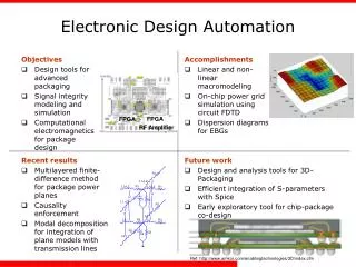
Physical Design Automation • Physical design automation refers to the computer-aided physical design cycle.
Design Styles • Full Custom • Utilized for large production volume chips such as microprocessors. • No restriction on the placement of functional blocks and their interconnections. • Highly optimized, but labour intensive. • Standard Cell • Utilized for smaller production ASICs that are generated by synthesis tools. • Layout arranged in row of cells that perform computation. • Routing done on “channels” between the rows.
Design Style • Gate Arrays • Pre-fabricated array of gates (could be NAND). • Design is mapped onto the gates, and the interconnections are routed. • Field programmable gate arrays • Pre-fabricated array of programmable logic and interconnections. • No fabrication step required.
Design Style • Sea of gates • Pre-fabricated sea of gates with no area for routing. • Simpler gates with very high density. • Routing through gates or by fabricating over the cell routing.
Packaging • Printed Circuit Boards • Packaged chips are soldered on a substrate. • Larger wire delays, lower integration. • Multichip Modules (MCM) • Un-packaged chips are soldered on a substrate. • Medium wire delays, medium integration. • Wafer Scale Integration • Multiple chips are fabricated on a single wafer. • High performance, high integration, lower yields.
Summary • VLSI Design Cycle was explained. • PDA defined, and introduced. • Overview of design styles and packaging.