Download
1 / 15
150 likes | 262 Vues
F.E.T.S. RFQ Support Structure by Peter Savage 21 ST October 2009. The welded RFQ section support frame. Made from box section mild steel. EN24 flat blocks x 2 EN24 vee blocks x2. Tops of strips and bottoms of feet to be machined flat and parallel. Total weight = 60kg.

E N D
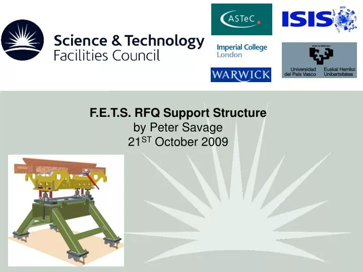
F.E.T.S. RFQ Support Structure by Peter Savage 21ST October 2009
The welded RFQ section support frame Made from box section mild steel EN24 flat blocks x 2 EN24 vee blocks x2 Tops of strips and bottoms of feet to be machined flat and parallel. Total weight = 60kg
Stress and deformation due to weight of RFQ Nodes: 22500 Elements: 9857 Quarter load: 75kg (300/4) Load applied: Top faces of pads Support 1: Frictionless at 2 symmetry planes. Support 2: Fixed under foot Material: Structural steel Mass: 60kg Results: Total deformation: 0.0027 mm Max equ. stress: 12MPa Safety factor: 20
The kinematics assembly Total weight = 12kg
The kinematic mount for the RFQ section Screw jacks allow for RFQ height adjustment and tilt by resting in: cone – allows rotation only flat – allows movement in horizontal plane vee – allows movement in one axis 2 3 Springs reduce judder when re-positioning RFQ sections 1 Complete kinematic assembly can be positioned by adjusting these screws
RFQ welded steel support cradle Total weight = 22kg Cradle must: Support the RFQ section Allow RFQ section to be mounted to the kinematics Allow the RFQ section to be lifted by crane.
Cradle + kinematics + main support Here the cradle is shown placed onto the kinematic system which in turn sits on the main frame. To adjust for height or tilt the screw jacks must first be unlocked by undoing the 3 nuts shown. To move the entire kinematic assembly in the horizontal plane these four nuts must first be undone
+/- 10mm +/- 10mm +/- 10mm +/- 10mm +/- 10mm
Case1: Under weight of RFQ Nodes: 31838 Elements: 12022 Half load: 150kg Load applied: Top of dummy RFQ. Support 1: Frictionless at symmetry plane. Support 2: Fixed at screw jack domes. Material: Structural steel Mass: 22kg (cradle + jacks) Results: Total deformation: 0.007 mm Max equ. stress: 11MPa Safety factor: 22
Case 2: Lifting RFQ Nodes: 31838 Elements: 12022 Half load: 150kg Load applied: Under hooks Support 1: Frictionless at symmetry plane. Support 2: Fixed at dummy RFQ top (not shown). Material: Structural steel Mass: 22kg (cradle + jacks) Results: Total deformation: 0.007 mm Max equ. stress: 10MPa Safety factor: 25