Download
1 / 24
240 likes | 247 Vues
m CAP. COMET (Com pressor for e t racking ) Overview. Data connections. ePC2 Anodes : 1024 Cathodes: 2 x 320. Bundles of 20 twisted pairs = 16 wires + threshold + power. ePC1 Anodes : 512 Cathodes : 2 x 192. Bundles of 20 twisted pairs = 16 wires + threshold + power. Cathodes

E N D
mCAP COMET (Compressorfor e tracking) Overview
Data connections ePC2 Anodes : 1024 Cathodes: 2 x 320 Bundles of 20 twisted pairs = 16 wires + threshold + power ePC1 Anodes : 512 Cathodes : 2 x 192 Bundles of 20 twisted pairs = 16 wires + threshold + power Cathodes 64 wires x 6 Anodes 64 wires x 8 Anodes 64 wires x 16 Cathodes 64 wires x 10 Controller 2xSIS3600 Controller 7 modules housing 128 wires each = 56 bundles of 16 wires 13 modules housing 128 wires each = 104 bundles of 16 wires 2x16 twisted pairs 1x10 twisted pairs 2x16 twisted pairs = 32 bits data words 1x10 twisted pairs = commands
A0 A1 B0 B1 A0 A1 B0 B1 Onecompressormodule Pulser board
Pulser Normalized puls of variable width The four preamplifiers connected to one FPGA are flashing together On pin 39 750 mV (cmd = 70) Linear up to 1V, then saturates Rise time = 100 ns Noise < 60 mV Fall time (t1/2) = 1500 ns Cathode pulse = positive polarity jumper on (+) Anode pulse = negative polarity jumper on (-)
Data : maximum flows, input impedances Clock 50MHz LVDS Twisted pairs 110 ohms Logic pulses Width > 25 ns LVDS Each SIS3600 has: Max rate: 20 Mo/s FIFO = 32 Kwords of 32 bits Full in 6.4 ms Data strobe period = 200 ns Controller Controller 26 FPGAs rate < 7.7 x 10⁵ words/s/FPGA rate < 6000 hits/s/wire FIFO = 512 words of 32 bits ECL ECL Twisted pairs 100 ohms Data width = 200 ns Strobe width = 65 ns
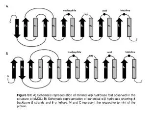
Block diagram inside one FPGA 32 bit words Time A word B word baff ffff date date date date date date bits bits bits bits bits bits bits bits bits bits bits bits bits bits bits bits 30 ns Time counter Clk*2 100Mhz Time_max = 224*30 ns=503 ms MUX Edge detection DataA (input 0/32) 32 Abits builder 32 bits sequence builder FIFO 512 k 32b words Pattern generator Test MUX Edge detection DataA (input 1/32) Tokin Readout sequence 200 ns period Mask Inhibit Tokout 32 Bbits builder Command for modes Data_out
Tokring Token in out in out in out in out in out in out Ctrl (Z) FPGA FPGA FPGA FPGA To SIS3600 FIFO FIFO FIFO FIFO DATA Data transfer to the SIS3600 FIFO Inspection time for one turn : DT = (2.7 + FPGA_Nbr + NbrOfDataWords x 0.2 ) x 10-6 s 65 ns Next Data 200 ns Data rate at which one FPGA_FIFO gets full : rate = 512 / DT Rate = 512 / (2.7 + n + 512*0.2) = 4.6 MHz data for one wire for one wire
Inhibit and Time_clears Generates several interrupts and several TCL - Overlap of data over blocks - TCl within a block …. The the time clears are real and connected to new started blocks Never a problem but dead time waiting the end of the 400 ms period. Problem to be taken very seriously …
Conclusion The problems were: Mismatch in resistor chain command bad input impedance for LVDS lines and crosstalk between inputs - cured by replacing all resistors at the input Spurious bad events… loss of data correct sequence baldly interpreted as time clears -cured by discovering that the length of the command cable played a role in the input impedance of the SIS3600 : (100 ohm in series) but also 2K resistors in parallel. - cured by removing the 2K resistors for the data and for the NEXT signal (! The SIS manual is wrong) - cured by recomputing the resistors in the ECL output driver Discovering of real time clears due to the external end and start of bocks… - to be studied in the ultimate DAQ. COMET works fine and fast … we need to be careful with the external logic.
Data flow and rate reductions 5 MHz Start TDC, ref. time, clocks, from master module p4 50 MHz Read and refresh rate 200 Hz 1 kHz Evt rate 10 kHz Data Channels Units Bits/evt Buffer size Acq. rate Muon channels: anodes mPC1 : 50 anodes mPC2 : 54 anodes TPC : 74 * 3 thres. cathodes TPC : 37 * 2 thres. 10 TDC400 out: data: 48 bits time 16 bits ~ 64*10*40 10k*64*400 = 32 MB/s 400 1.536MB Tmax = 13.1 ms VME bus # mSC anode: 1 # mSC_A anode: 1 2 > 4*32 < 8*32 20 Compressors out: data 32 bits time+code 32 bits I.R. < 10k*8*32 = 320 kB/s ePC1 & ePC2 channels: anodes : 1536 cathodes : 1024 40kB 2560 = 20*128 Tmax = 419 ms # eSC1 anodes: 32 # eSC2 anodes: 32 10k*5*32 = 200 kB/s 5*32 1 TDC V767 64 128kB Tmax = 1.7 ms
32 inputs 32 inputs 32 inputs 32 inputs 32 edge detectors 32 edge detectors 32 edge detectors 32 edge detectors ePC 128 channel compressor unit, dead-time free > 20 ns < 80 ns 50 Mhz clk input Logic Div 1/5 A Time counter Data Z-1 FIFO B Time + code 32 bits A 32 bits B Time + code 32 bits D Time + code 32 bits C Time + code 32 bits A ...... ...... Bits: Time : 22 bits => 419 ms Code : unit nbr ( 5 bits) connectors (4 bits) Unused : 1 bit Data : 32 Buffer size : 512 words Evt nbr (3w) : = 170 Filling time : > 17 ms at 10 kHz Z-1 C Z-1 Circular check of the content and emptying commands A To VME I.R. buffer
19 inch ePC full compressor Clk ePC 128 ch compressor Control bus ePC 128 ch compressor MASTER MODULE Div 1/10 5 MHz ePC 128 ch compressor Circular checker of the 20 buffer status in ePC compressors and readout controller Div 1/50000 1 kHz Clk 50 MHz 20 units VME bus extra VME CRATE VME I.R. SIS3600 32 bits input FIFO : 128 kB Speed: 20 MB/s Data bus ePC 128 ch compressor
Option 1: compressor without VME protocol Clk P1 Tranceiver Reset Ovfl Tranceiver FIFO Data EPF 10K50 VME BUS Tranceiver Strobe Token in P2 Tranceiver Token out JTAG Cost : EPF 10K50 -1 $250 PCB $100 Tranceivers & drivers $ 50 Mechanics & conn. $150 TOTAL (tax free) : $550 * 20 + spare + tax = $ 14000
Option 1: master board, no VME protocol 5 MHz output Div 1/10 1 kHz output Div 1/50000 Clk 50 MHz Clk Ext clk input Reset Reset P1 Ovfl Strobe VME BUS 32 bits output to Input Register max rate :20 MB/s Data Tranceiver Return token P2 Start token Micro Processor On/off Init Loading flash memory JTAG Flash memory Cost : Processor $ 50 PCB $800 Tranceivers & drivers $ 50 Mechanics & conn. $150 TOTAL (tax free) : $1050 + tax = $ 1300
Option 2: compressor with a VME protocol Clk Reset P1 EPF 10K30 Tranceiver FIFO Tranceiver Data VME BUS Tranceiver P2 Tranceiver FPGA for VME protocol JTAG Cost : EPF 10K50 -1 $250 FIFO 2k 32 bits $ 63 EPF 10K30 -1 $ 70 PCB $100 Tranceivers & drivers $ 50 Mechanics & conn. $150 TOTAL (tax free) : $683 • More general BUT • much more man work • more complex in data acquisition • 20 times more interrupts • multiple data flow in Ethernet * 20 + spare + tax = $ 18000
Sequences in the edge detection > 20 ns 20 ns Time 1 2 3 4 5 6 7 8 Cells 1 2 3 4 5 6 7 OR 0 0 0 not3 and2=0 0 0 0 0 0 1 0 0 not3 and2=0 0 0 0 0 0 1 1 0 not3 and2=1 0 0 0 0 1 1 1 1 not3 and2=0 1 0 0 0 1 1 1 1 not3 and2=0 0 1 0 0 1 1 1 1 not3 and2=0 0 0 1 0 1 0 1 1 not3 and2=0 0 0 0 1 1 1 0 1 not3 and2=0 0 0 0 0 0 0 1 0 not3 and2=1 0 0 0 0 1 0 0 0 not3 and2=0 1 0 0 0 1 1 2 34 5 6 7 8 9 10 Time
COMET bus VME SIS3600 SIS3600 Half Full C O M P R E S S O R C O M P R E S S O R C O N T R O L L E R Time Clear Inhibit 01 20 Ctrl bus 8X 16 wires RS232 8X 16 wires Data bus (32 bits) 2560 wires COMET block drawing
Normal Normal 15 15 31 31 31 31 Testmode Testmode A Pulsmode Pulsmode 0 0 Token Token 16 16 16 16 RdEmpty RdEmpty 15 15 A A B B B 0 0 Full Full - + - + Compressor Layout Ch0 Ch0 P1 A FPGA B - + - + Ch1 Ch1 P2 FPGA Front view Side view
Ready Strobe Inhibit FPGA Full VME Full 16 32 Test Data Mark 1 17 Ext Clk TimeClr 8 Control 1 + Controller Layout P1 CPU FPGA Ext Int P2 - + - + Front view Side view
Onecompressormodule A1 A0 B0 B1 A1 A0 B0 B1