Download
1 / 42
440 likes | 729 Vues
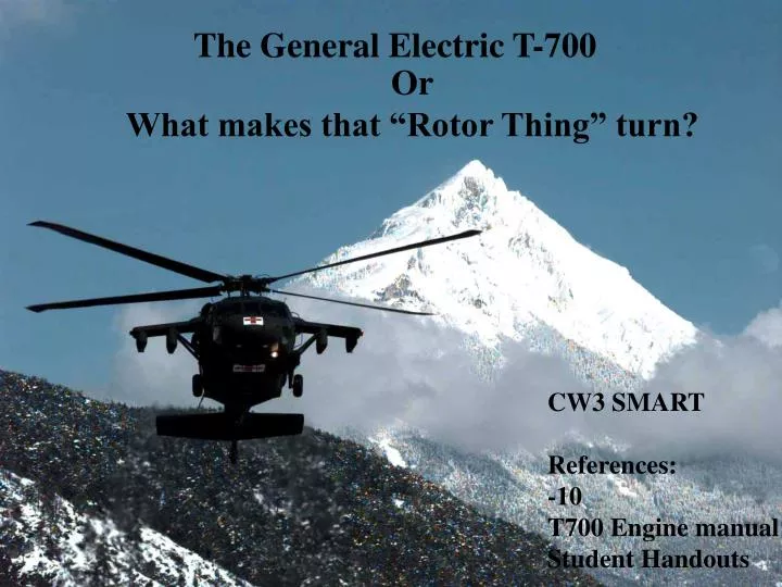
The General Electric T-700. Or What makes that “Rotor Thing” turn?. CW3 SMART References: -10 T700 Engine manual Student Handouts. OBJECTIVE. Develop student instructor pilots understanding of the GE T-700 engine. Topics. History and development IAW FTG Schedule

E N D
The General Electric T-700 Or What makes that “Rotor Thing” turn? CW3 SMART References: -10 T700 Engine manual Student Handouts
OBJECTIVE Develop student instructor pilots understanding of the GE T-700 engine.
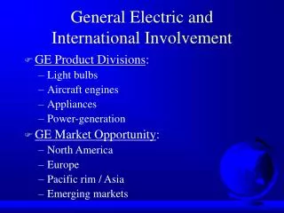
Topics History and development IAW FTG Schedule Electrical control unit (ECU) Hydromechanical unit (HMU) Pressure and overspeed unit (POU) NP overspeed protection Engine Alternator
ENGINE CHARACTERISTICS • Output power: 1,543 SHP (sea level standard day) • Type of compressor: 5 stages axial, 1 centrifugal • Variable geometry: IGV+ stage 1&2 stator vanes • Engine weight: 415 LBS • Time between overhaul: none(on condition)
HISTORY&DEVELOPMENT The T700 engine design is directed at minimizing required maintenance Maintenance tasks have been simplified Corrective maintenance is on on a “on condition” basis Modular design allows sub-system replacement
HISTORY CONTINUED: • Lock wire elimination • Tool requirements reduced • LRU’s • External lines reduced • HMU no Rigging • Dual sided sight glass and “impending” bypass indicators
ENGINE MODULES • Cold section • Hot section • power turbine module • Accessory module
COLD SECTION • Includes the inlet comprised of , swirl frame, main frame, front frame, and scroll case. These together with the inlet duct and blower make up the Inlet. • Compressor section, diffuser and midframe. • Hot air and oil provide anti-icing • Scroll vanes act as air/oil cooler supplementing the fuel/oil cooler • 100% NG=44,700 RPM
HOT SECTION • Consists of combustion liner, #1 stage nozzle assembly, and the gas generator turbines. • Gas generator turbines rotor drives the compressor • 12 fuel injectors, 2 primer nozzles, and 2 igniters
POWER TURBINE MODULE • Comprised of the power turbine rotors, power turbine driveshaft, power turbine case, the #3 and #4 nozzles, and the exhaust frame. • Expanding exhaust gases exiting drives the free power turbine at 20,900 RPM=100%NP • Casing support the 7 TGT Thermocouples and the NP/torque sensors
ACCESSORY MODULE • Mounts to the cold section module and is driven off the compressor section by a PTO via a radial driveshaft. • Provides drive and mounts (pads) for engine components
ECU….. WHAT’S IT DO? • Trims the HMU NG governor through the tq motor within acceptable engine limits to maintain isochronous NP governing. This can be overridden ONLY by TGT limiting. • Exchanges tq signals to provide automatic load sharing for multi-engine use. • Provides signal to the POU for NP overspeed protection 106+- 1% • Provides cockpit signals, NP, TGT, TQ
ECU FUNCTIONS, OR CHECK RIDE ANSWERS ? • Np reference from cockpit • Overspeed signal to POU (redundant power,TQ SIGNAL) • TGT limiting, 837-849 • Signals to cockpit, TQ, TGT, Np • History recorder signal • Isochronous NP governing(will maintain ref.) • Torque load sharing
HMU DESCRIPTION • Mounted on the aft center of the AGB • Receives filtered fuel through cored passages in the AGB • High pressure vane type pump. Max 832 PSI
HMU FUNCTIONS • Collective pitch compensation (LDS) • Acceleration/deceleration flow limiting • Ng limiting (Governing & shutdown) • Torque motor to trim NG governor • PAS override (lockout) • Fuel pumping • Fuel metering • Variable geometry positioning • Vapor vent (priming)
POU DESCRIPTION • The Pressurizing and overspeed unit is mounted on the aft, left hand side of the AGB • 3 outlets. Start fuel manifold, main fuel manifold, and overboard drain (+bypass during overspeed) • 3 inlets. Fuel through AGB core, P3 air, overspeed signal
POU FUNCTIONS • Sequences fuel to start fuel manifold (2) • Sequences fuel to main fuel manifold (12) • Purges start fuel manifold and nozzles during start, and main fuel manifold and nozzles during shutdown • Provides NP overspeed protection when activated from the ECU overspeed circuit
ALTERNATOR DESCRIPTION • Mounted on the right hand forward side of the AGB • Provides power to all essential engine functions • output consists of 3 individual signals (windings) • May fail independently or as a unit
ALTERNATOR FUNCTIONS(BY WINDING) • Provides power to the ignition exciter • Provides power to the ECU • Provides NG signal to the cockpit
NICE TO KNOW STUFF • BLUE=OVERSPEED • GREEN=COCKPIT SIGNALS • BLACK=ENGINE IGNITION • YELLOW=ENGINE ELECTRICAL FUNCTIONS
ENGINE EP’S • FAILURE • LAUNDRY LIST • COMPRESSOR • SHAFT • INCREASE/DECREASE/TQ SPLIT
LIMITS • OIL TEMP • OIL PRESS • NG • NP • TGT -50-135/135-150 20-100/35-100 0-99/99-102/102-105 91/95-101/101-105/105-107 0-775/775-850/850-886
SUMMARY • The T700 is closely integrated with helicopter components to provide proper power output for each flight condition • The system functions automatically, with no pilot action required after starting • Engine control is functionally split between the HMU and ECU. The HMU provides functions for safe operation, and the ECU performs a fine trim to reduce pilot workload • The system is self contained and engine powered