Download
1 / 76
860 likes | 2.39k Vues
Gain insights into the world of embedded systems, exploring design challenges, processor technology, and trade-offs. Learn about single-purpose processors, general-purpose processors, and the characteristics of embedded and real-time systems.<br>

E N D
EMBEDDED SYSTEMS 1 Prof. Ch.Ramesh Embedded Systems
INTRODUCTION Embedded system technology over view design challenges Processor Technology IC Technology design Technology Trade-offs. Single purpose processors: RT, Level combinational logic, sequential logic( RT level), Custom single purpose processor design (RT Level), optimizing custom single processors. General purpose processor : Basic architecture, pipelining, programmers view, development environment, ASIPS, microcontrollers and DSPs. 2 Prof. Ch.Ramesh Embedded Systems
Embedded system over view Design challenges Processor Technology IC Technology Design Technology Trade-offs. 3 Prof. Ch.Ramesh Embedded Systems
System : A system is a way of working , organizing, or doing one or many tasks according to a fixed plan, program, or set of rules. A system can also an arrangement in which all its units assemble and work together according to the plan or program. Eg: Computer system consists of A micro processor A large memory comprising of a. Primary memory (RAM, ROM, and fast accessible caches.) b. Secondary memory (magnetic memory, tapes, and optical memory) Input output Networking units. 4 Prof. Ch.Ramesh Embedded Systems
Embedded /real System : An embedded system is the one that has a computer hardware with software embedded in it as one of its most important component to operate in real time is called real time system. An embedded system has soft ware designed to keep in view of the three constraints: Available system memory Available processor speed Need to limit power dissipation when running the system continuously. in cycles of wait run stop wakeup events. 5 Prof. Ch.Ramesh Embedded Systems
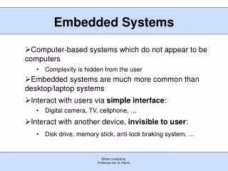
Cell phone camera Antenna Aero space communication Examples of Embedded Systems: Mobile computing b. Banking c. Defense d. Automobile e. Networking systems f. Digital Cameras g. High Definition TVs h. Robotics in Assembly Note: The embedded systems are scattered into so many areas. Hence it is used in small applications like home appliances to a very sophisticated applications 6 Prof. Ch.Ramesh Embedded Systems
Characteristics of Embedded/Real Time Systems: • 1. Single functioned • 2. Tightly constrained • 3. Reactive and real time 7 Prof. Ch.Ramesh Embedded Systems
Single functioned: An embedded system usually executes a specific program repeatedly Case 1: a desk top computer executes a variety of programs like spread sheets, word processors and video games etc.. The embedded system program is updated with a new version. Case 2: Several programs are swapped in and swapped out of a system due to size limitations. Example: missile run one program cruise mode then load a second program form locking onto a target. All the above exceptions represent a specific function. 8 Prof. Ch.Ramesh Embedded Systems
Tightly Constrained: All computing systems have constraints on design metrics, but those on the embedded systems can be especially tight. The design metric is a measure of an implementation features such as cost ,size ,performance and power. Embedded systems can be of Low cost, size fit into single chip they are fast enough to meet the requirements and must consume less power. To extend battery life and prevent the necessity of cooling fan. 9 Prof. Ch.Ramesh Embedded Systems
REACTIVE AND REAL TIME: Many embedded systems must continuously react to changes in the systems environment and must compute certain results in real time without delay. Eg: cars cruise controller continually monitors and reacts to speed and break sensors. It must compute acceleration and deceleration repeatedly with out delay or in a limited time. 10 Prof. Ch.Ramesh Embedded Systems
CLASSIFICATION OF EMBEDDED / real time SYSTEMS • Small scale systems • Medium scale system • Sophisticated systems 11 Prof. Ch.Ramesh Embedded Systems
Small scale embedded systems: The systems are designed with a single 8 or 16 bit microcontrollers they have little hardware and software complexities. The main programming tools for small scale embedded systems are editor, cross assembler specific to a microcontroller. The software has to fit within the memory available and keep in view the need to limit the power dissipation when system is running continuously. 12 Prof. Ch.Ramesh Embedded Systems
Medium scale embedded system: These are designed with a single or few 16-32 bit microcontrollers or DSPs are RISCs. They have both software and hardware complexities. The sources of programming for medium scale Embedded systems are RTOS, Source coding tools, simulator, debugger and Integrated Development Environment, These systems may also employ the readily available ASSP ( Application Specific System Programming) and IP for various functions. 13 Prof. Ch.Ramesh Embedded Systems
Sophisticated Embedded systems 1. Sophisticated Embedded systems have enormous hardware and software complexities and may need scalable processors or configurable processors and programmable logic arrays. 2. They are used in cutting edge applications that need hardware and software co design and integration in the final system. 3. TCP/IP Protocols stacking and network driver functions are implemented in the hardware to obtain additional sppeds by saving time. 14 Prof. Ch.Ramesh Embedded Systems
Design Challenges The embedded systems designer must construct an implementation that fulfills desired functionality. The following are the design metrics of Embedded Systems 5. Flexibility 6. Time to market 7. Maintainability 8. Safety NRE Cost ( Nonrecurring engineering Cost) Unit Cost Size Performance 15 Prof. Ch.Ramesh Embedded Systems
Metrics: Improving the metrics of one will worsening the another. Eg: Size reduction Adapting to new technologies 3. Familiarization with new HW and SW If we reduce the an implementation size the implementation performance may suffer. To meet this optimization challenges the designer must be comfortable with a variety of hard ware and software implementation technologies. The designer must be able to migrate from one technology to another Technology in order to find the best implementation. 16 Prof. Ch.Ramesh Embedded Systems
Time to market design metric: Time to market constraint has become especially demanding in recent years. The above figure shows the simple market window The product would have highest sales Further if we look in to window there is a loss of sales. Revenues ( $) Time in months 17 Prof. Ch.Ramesh Embedded Systems
Peak revenue Market rise Peak revenue from delayed entry On time Market Fall Delayed 2W A W Time D On time entry Delayed Entry Loss of revenue can occur due to a delayed entry of product. Adding the difficulty of meeting the time to market constituent 18 Prof. Ch.Ramesh Embedded Systems
NRE ( Non Recurring Engineering Cost) and unit cost design metrics Assume there are three technologies $200,000 $200 $160,000 $160 Total Cost $120 $120,000 Per product Cost $80,000 $80 $40,000 $40 800 1600 2400 800 1600 2400 Number of units (volume) Number of units (volume) 19 Prof. Ch.Ramesh Embedded Systems
By ignoring all other choice of metrics the best technology choice will depend on the number of units that are planned to produce. The same is illustrated with a graph. Total cost = NRE Cost + unit cost * # of units. The cost per product is also calculated. • Performance design metrics: • Performance of a system is a measure of how the system takes to execute our desired tasks. • The measure of performance depends on the following: • 1. Latency or response time • 2. Throughput • Latency :The time between the start of the task execution and the end. • Throughput: the number of tasks that can be produced per unit time • The common method of comparing is to spedup of two systems 20 Prof. Ch.Ramesh Embedded Systems
PROCESSOR TECHNOLOGY • Processor technology relates to the architecture of the computation engine used to implement a system desired functionality. • General purpose processors and software • Single purpose processor and hardware • Application specific processors • General purpose processors - software: • It is a programmable device suitable for a variety of applications to maximize the number of devices sold. • 1. Program memory • 2. General data path • 3. General purpose ALU • An embedded system designer simply uses a general purpose processor by programming the processor memory to carry out the required functionality.` 21 Prof. Ch.Ramesh Embedded Systems
Single purpose processors: A single purpose processor ia a digital circuit designed to execute exactly one program. The embedded system designer must create a single purpose processor bny designing custom digital circuit. Another common terms include are : coprocessor , accelerator, peripheral Single purpose processors benefits: 1. Performance is fast 2. Size and power is small 3. Unit cost is low 4. Performance may not match with general purpose processors The architectures of different processors are given below. 22 Prof. Ch.Ramesh Embedded Systems
Controller Controller Data path Data path Control logic and state registers Control logic and state registers Registers Register File General ALU CustomALU IR IR PC PC Program Memory Program Memory Data Memory Data Memory Assembly Code Assembly Code Total = 0 For I = 1 to --- Total = 0 For I = 1 to --- General Purpose processor Application specific processor Single Purpose processor Controller Data path Control logic Index Total state registers + Data Memory c b a 23 Prof. Ch.Ramesh Embedded Systems
Application specific Processors: It is a programmable processor optimized for a particular class of applications having common characteristics such as embedded control, digital signal processing, telecommunication applications. The designer of the processor can optimize the data path for the application class. ASIP is an embedded system that can provide the benefit of flexibility while achieving good performance. Examples are microcontrollers, digital signal processors etc. 24 Embedded Systems
IC Technology Full custom VLSI Semi custom ASIC ( Gate Array and Standard Cell) PLD 25 Prof. Ch.Ramesh Embedded Systems
DESIGN TECHNOLOGY • Design technology invloves in which we convert our concept of desired system functionality to an implementation. • We must not only design the implementation to optimize design metrics but we must do so quickly. • The design process involves top down design process . The designer refines the system through several abstraction levels • The designer go through the following • System specification • Behavioral specification • Register transfer specification • Logic specification 26 Prof. Ch.Ramesh Embedded Systems
System specification : The designer describes the desired functionality in some language. Often in natural language or preferably in executable language is known as system specification Behavioral specification: The designer refines this specifications and by distributing portions of programs among general or single purpose processors is known as behavioral Specifications for each processor. 27 Prof. Ch.Ramesh Embedded Systems
RT specifications: Converting the behavior on general purpose processors to assembly code and by converting the behavior on single purpose processor to a connection of register transfer components and state machines. Logic specification: The designer refines the register transfer level specifications of a single purpose processors into a logic specification consisting of Boolean equations. 28 Prof. Ch.Ramesh Embedded Systems
System Specification behavioral Specification RT Specification Logic Specification To final implementation 29 Prof. Ch.Ramesh Embedded Systems
The various approaches to improve the process for increased productivity. Each approach can be applied at any of the four abstraction levels they are COMPILATION/ SYNTHESIS LIBRARIES/ IP TEST/ VERIFICATION MORE PRODUCTIVITY IMPROVERS 30 Prof. Ch.Ramesh Embedded Systems
31 Prof. Ch.Ramesh Embedded Systems
Tade-offs The choice of hard ware and soft ware for a perticular function is simply a trade off among various design metrics. 32 Prof. Ch.Ramesh Embedded Systems
Custom Single Purpose Processors: Hardware Processor: A processor a digital circuit designed to perform computation tasks. A processor consists of data path capable of storing and manipulating data and a controller capable of moving data through a data path. Single purpose processor: The single purpose processor designed specifically to carry out a perticular computational task. An embedded system designer may obtain several benefits by choosing to use a custom single purpose processor rather than a general purpose processor to implement a computation task. Basic techniques in designing a single purpose processors 33 Prof. Ch.Ramesh Embedded Systems
Combinational logic. • Sequential logic. • Custom single purpose processor design. • RT- Level Custom single purpose processor design. • Optimizing Custom single purpose processor design. 34 Prof. Ch.Ramesh Embedded Systems
Combinational Logic • Transistors and Logic Gates • Basic combinational Logic Design • RT – Level Combinational Components 35 Prof. Ch.Ramesh Embedded Systems
Transistors and logic gates: The transistor is the basic electrical component in a digital system. The transistor acts as a simple on/off switch. Eg : CMOS ( Complementary Metal Oxide semiconductor) The Gate controls whether or not the current flows from the source to the drain. Given the basic two transistors we can construct the following digital family gates. 36 Prof. Ch.Ramesh Embedded Systems
Source Source Conducts if gate = 1 Conducts if gate = o Gate x Gate x y y F=(xy)| Drain F=(x+y)| Drain x x y y e d a b N MOS Transistor N MOS Transistor Inverter NAND gate NOR gate X F=X c 37 Prof. Ch.Ramesh Embedded Systems
Different types of gates used in digital systems are Driver gate Inverter And gate Nand gate Or Gate Nor Gate Exclusive OR gate Exclusive NOR gate 38 Prof. Ch.Ramesh Embedded Systems
Basic Combinational Logic Design A combinational logic circuit is a digital circuit whose output is purely a function of its present inputs. Such a circuit has no memory of past inputs. We use a simple technique to design a combinational circuit from basic logic gates. Minimize the output equation to minimize the number of gates used and draw the circuit diagram. Eg : 39 Prof. Ch.Ramesh Embedded Systems
abc bc y z bc y 1 1 1 a a 1 1 1 1 1 1 1 z Y = a|bc + ab|c + abc| + abc Z = a|b|c + a|bc| + abc| + abc 40 Prof. Ch.Ramesh Embedded Systems
I(m-1) I0 s0 N bit m X 1 Multiplexer Slog(m) n O RT- Level Combinational Components: There are several combinational components to reduce the computational complexity. The combinational components include 1. Multiplexer 2. Decoder 3. Adder 4. Comparator 5. Arithmetic Logic Unit Multiplexer: This is sometimes called as selector. It allows only one of its data inputs to pas through to the output. If there are ‘m’ data inputs then it has log 2m select lines. We call this as m X 1 mux. 41 Prof. Ch.Ramesh Embedded Systems
I(log(n) – 1) A I2 I1 I0 B N – bit adder Log(n) X n Decoder On-1 O2 O1 O0 Carry Sum Decoder: A decoder converts a binary input into one hot output. If there are n outputs then there must be log2(n) inputs. The decodes is called log2(n) X n decoder. It has an additional input called enable input. Adder: Adds two n bit numbers A & B generating n bit output sum and a carry. An adder comes with carry as input such adders can be cascaded to produce n bit adder. 42 Prof. Ch.Ramesh Embedded Systems
A B Comparator: A comparator compares two n bit binary inputs A and B and generating outputs that indicate whether A is less than grater than or equal . Accordingly the outputs are generated. n – Bit Comparator Less Equal Greater Arithmetic Logic Unit: It can perform different types of arithmetic and logic functionson the given input bits of A & B. The select lines are used to select the current function. A B so N bit m function ALU s1 S(log m) sum 43 Prof. Ch.Ramesh Embedded Systems
In the design of ALU define the basic operations of ALU ans define the status of status signal . Consider the ALU performs the following operations 44 Prof. Ch.Ramesh Embedded Systems
45 Prof. Ch.Ramesh Embedded Systems
Sequential Logic • The components of sequential logic are : • 1. Flip – Flops • 2. RT – Level Sequential Components • 3. Sequential Logic Design 46 Prof. Ch.Ramesh Embedded Systems
Flip-Flops : A sequential circuit is a digital circuit whose outputs are a function of the present as well as previous input values. One of the most basic sequential circuits are Flip – Flops A Flip – Flop stores single bit. The simplest type of flip flop is D type Flip Flop. When the clock is zero the D input is ignored and the out put continue to reflect the stored value. Another type of Flip – Flop is SR type Flip – Flop Other Flip – Flop is JK type of Flip Flop where when JK inputs are 1 then the stored bit toggles from 1 to 0 or 0 to 1. To prevent unexpected behavior from signal glitches the Flip – Flops are designed to be Edge triggered Flip – Flop. 47 Prof. Ch.Ramesh Embedded Systems
n Load n Bit Register Clear n Q RT-Level Seqential Coponents • The components of RT – Level Components are : • Registers • Shift Registers • Counters Register : A register stores ‘n’ bit data input and these stored bits appear at its output Q. A register has at least two control inputs i.e. Clock and load. For rising edge triggers register the input I are only stored when load is 1 and clock is rising from 0 to 1. the clock is usually drawn as small triangle as shown ion figure. Because all n bits of the register can be stored in parallel we often refer this type of register is called Parallel Load Register. 48 Prof. Ch.Ramesh Embedded Systems
shift n-bit shift register Q = lsb clock I Shift Register: It stores n bits but it cannot store them in parallel. The bits must be shifted into the register serially. i.e. one bit per clock. A shift register has one bit data input and has two control pulses. i.e. clock and shift. When clock is rising and shift is 1 then the input value is stored in nth position by shifting the nth position bit to n-1 position and so on. The fist bit that is shifted out will appear at the output Q. 49 Prof. Ch.Ramesh Embedded Systems
N bit counter Counter Count Clock Clear n Q A counter is a register that can also increment meaning ad 1 to it. A counter has a clear input which resets the counter to 0. The count input enables the incrementing on each clock edge. It has the options to up count and down count. The control inputs are either synchronous are asynchronous. 50 Prof. Ch.Ramesh Embedded Systems