Download
1 / 35
380 likes | 663 Vues
Embedded Systems. Introduction 09/10. Embedded Systems 16-5147. Alan Holloway contact: a.f.holloway@shu.ac.uk Room 9323 Furnival 12 × 1 Hour Lectures 12 × 2 Hour Labs (staffed for 1 Hours) 100% Coursework formative series of lab tutorials (10%) 5 × Homework questions ( 2% each )

E N D
Embedded Systems Introduction 09/10
Embedded Systems 16-5147 Alan Holloway • contact: a.f.holloway@shu.ac.uk • Room 9323 Furnival • 12 × 1 Hour Lectures • 12 × 2 Hour Labs (staffed for 1 Hours) • 100% Coursework • formative series of lab tutorials (10%) • 5 × Homework questions ( 2% each ) • major assignment (80%)
Resources • All course information can be found at www.aholloway.co.uk follow link for this unit • Lecture notes • Sample programs • Reading list • Software (available free)
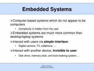
What is an embedded system? • An embedded system is a special-purpose computer system designed to perform one or a few dedicated functions • Washing machine runs programs • Open water valve • Heat water • Start spin • etc etc…. • Do we need a PC running windows Vista to do this ?
Will I ever need to use one? • Over 4 billion 8-bit microcontrollers were sold in 2006 alone • the world's population is estimated to be about 6.756 billion • Average car contains >50 microcontrollers • Electrical, electronic, control, robotics, computer engineer - Yes you will
Embedded Systems • Microprocessor Systems • Microcontrollers • ARM7 core Processor Family • specifically NXP LPC2368 microcontroller • Many others are available 8051, PIC, AVR etc • C Programming will be used throughout • ARM Realview MDK - 'C' compiler & other tools • u-Vision Integrated Development Environment
Microprocessor system • CPU • Memory – ROM and RAM • Input – various • Output - various
Bus system • Devices connect to microprocessor via bus system (often called the memory bus) • A devices connected to bus must be tri-state devices • only one device is activated at a time • Consists of 3 bus types • Address bus • Data bus • Control bus
address decoder chip enable signals address bus data bus a d CE CE CE reset Additional devices uP ROM RAM I/O clock OE WR OE WR OE read write Microprocessor System Structure
Bus operations • Read • Write • Each read/write operation is made up of a number of clock cycles or T states • Each machine instruction is made up of one or more read and/or write operations • This is why we shouldn't compare microprocessors simply based on clock speed
2a - 1 Totalmemory space 1 0 d bits Address Bus • Unidirectional and generated by microprocessor • Number of address lines determines number of address locations • Addressable locations = 2^a where a is the number of address lines FFFFH memory addresses E00FH I/O E000H Memory Map : A memory map shows the position of devices within the whole of the addressable area MemoryAddress 7FFFH RAM 6000H 3FFFH ROM 0000H
Data Bus • Bi-directional • Usually matches the word length of the microprocessor • Usually a multiple of 8 • We talk of 8-bit, 16-bit , 32-bit and 64-bit processors which refers to the normal word length of the microprocessor
Control bus • Consists of potentially many signals. Typically:- • Read • Write • Could be single signal - Read/notWrite line • Interrupt control • Bus control signals for DMA (Direct Memory Access)
Microprocessr • CPU – Central Processing Unit • ALU – Arithmetic Control Unit • Registers • Control Unit
Microprocessor Registers • General purpose registers • Accumulator – used in conjunction with ALU – often found on 8-bit microprocessors • Status or Flag Register – indicate result of last instruction executed • Program counter(PC) or Instruction Pointer • Stack Pointer (SP) • Special registers – Instruction and memory address register
The Fetch – Execute cycle • Fetch • memory read cycle • place in instruction register and decode • Execute • may involve additional read and/or write cycles • Often the whole Fetch-Execute cycle is carried out through a pipeline operation involving several stages. • 5 stages are often used (IF, ID, RR, EX, WB) • The Pentium 4 has 20 stages • The ARM 7 has 3 stages
Pipeline - Natural assembly line • Example • Alan (A) Barry (B) & Chris (C) each have a load of clothes • Washer takes 30 mins • Dryer takes 30 mins • Ironing takes 30 mins A B C
Sequential - non pipelined B C 7pm 11.30pm A Total for 3 Loads is 4.5 Hours
Pipelined • Total for 3 loads pipelines 2.5 hours B C 7pm 11.30pm A
Pipelines • Does not speed up 1 task - increases overall throughput • Multiple tasks operate simultaneously using separate resources • Limited by speed of slowest resource
ARM7 Pipeline • The pipeline has hardware-independent stages that execute one instruction while decoding a second and fetching a third. The pipeline speeds up the throughput ofCPU instructions so effectively that most ARM instructions can be executed in a single cycle. • The pipeline works most efficiently on linear code.
CPU operation • On reset – PC is loaded with a value, typically 0 • Fetch – execute cycle • Fetch instruction • memory read cycle using PC (program counter) • place in instruction register and decode • increment PC ready for next fetch • Execute instruction • often involves additional read and/or write cycles to read operands and possibly write back results • could modify PC – causes flow of program execution to change
CPU Architecture • Two basic types • Von Neumann • One memory space for instructions and data • Therefore one single memory bus structure • Harvard • Separate instruction and data spaces • Therefore separate memory buses – parallel operation and therefore faster operation • Can have different address and data bus widths optimised for each bus
Basic microprocessor system • Von Neumann Architecture Microprocessor Power on & manual reset Address Reset Memory (Instructions & Data) and Input/Output A0-Ax Data Clock D0-dy Oscillator Read Write
Harvard Architecture Microprocessor Address Address Program Memory A0-Ax Data Memory & I/O A0-Ay Data Instruction d0-dn I0-Iw Read Read Write
Microcontroller • A microcontroller is the integration of • microprocessor • memory • ROM types – commonly flash PROM • RAM – Static ram • peripherals • parallel input and output(digital I/O) • Timers and Counters • Serial input and output (UART, USART, SPI etc.) • Analogue to digital converters • PWM, CAPCOM registers, DACs etc.etc.
What is an Embedded Computer System • Special purpose computer – usually with one specific task or application. • Usually embedded in a device which often has other electronic and mechanical parts • Usually optimised for the specific task • Has the usual basic computer components – CPU, memory, inputs & outputs
Examples • consumer appliances • tv's, mp3 players, dvd's, washing machines etc. • automotive applications • engine management, anti-lock braking • computer peripherals • hard disk controllers, routers, switches • medical equipment • scanners, blood analysers • telecoms • mobile phones • aerospace • satellite control systems, avionics
Some Characteristics • Very simple to very complex applications • Often single application • but concurrent operation • Could be real-time (hard and soft) • Program is normally stored in ROM – called firmware – flash ROM commonly • Could be critical applications • Interfacing with other devices via peripherals • Require a range of development tools – hardware and software • May use operating system (RTOS)
Constraints • Physical size • Weight • Power usage • Performance – throughput and/or response time • Cost
Resulting in - • limited space • limited processing power • 8-bit processor • limited memory RAM & ROM • only Ks of memory not Ms • schemes to limit power consumption • low power modes • sleep • standby • determinism – needed for RT guarantee
Microprocessor vs Microcontroller vs Soc vs FPGA • uP • General purpose • external memory and peripherals • connected by a memory bus • uC • uP integrated with memory and peripheral interfaces • families of uC all with same uP but varying amounts and types of memory and interfaces.
Microcontroller (µC) vs. Microprocessor (µP) • µC intended as a single chip solution, µP requires external support chips (memory, peripheral interfaces etc.) • µC has on-chip non-volatile memory for program storage, µP does not. • µC has more interface functions on-chip (serial interfaces,Analog-to-Digital conversion, timers, etc.) than µP • General purpose µPs are typically higher performance (clock speed, data width, instruction set, cache) than µCs • However the division between some µPs and some µCs becoming increasingly blurred.
FPGA/PLD • A field-programmable gate array is a semiconductor device containing programmable logic components called "logic blocks", and programmable interconnects. Logic blocks can be programmed to perform the function of basic logic gates such as AND, and XOR, or more complex combinational functions such as decoders or simple mathematical functions. In most FPGAs, the logic blocks also include memory elements, which may be simple flip-flops or more complete blocks of memory
Microprocessor vs Microcontroller vsSoCvs FPGA • SoC – System on a chip • FPGA – Field Programmable Gate Array Core Microcontroller-based System-on-a-Chip Rest of FPGA contains standard logic