Download
1 / 38
460 likes | 692 Vues
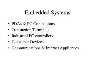
Embedded Systems. Computer-based systems which do not appear to be computers Complexity is hidden from the user Embedded systems are much more common than desktop/laptop systems Interact with users via simple interface : Digital camera, TV, cellphone, …

E N D
Slides created by: Professor Ian G. Harris Embedded Systems • Computer-based systems which do not appear to be computers • Complexity is hidden from the user • Embedded systems are much more common than desktop/laptop systems • Interact with users via simple interface: • Digital camera, TV, cellphone, … • Interact with another device, invisible to user: • Disk drive, memory stick, anti-lock braking system, …
Slides created by: Professor Ian G. Harris Tight Constraints • Embedded design methodology: Be Efficient! • Majority of embedded products are in cost critical markets (i.e. consumer electronics) • Other applications are in performance/power critical markets (i.e. military, medical) • Constraints include: • Maufacturing cost, Design cost, Performance, Power, Time-to-Market • Very different from traditional software engineering • Moore’s law will save you eventually • Embedded system designers should be control freaks • Need to have explicit control over timing, memory • Why trust a compiler/interpreter/OS?
Slides created by: Professor Ian G. Harris Application Specificity • Embedded systems are generally application-specific • Perform one task or set of related tasks • Some devices blur the line (i.e. cell phones) • Allows design to be focused on one application • Unlike general-purpose systems (i.e. laptop) • Higher design efficiency is possible • Special-purpose vs. general purpose (i.e. video games)
Slides created by: Professor Ian G. Harris Hardware/Software Codesign • Hardware and software are often designed together • General-purpose systems use HW and SW developed by different companies • Greatly improved optimization is possible • Include only HW/SW needed for your application • More work for the designers • Must understand both HW and SW
Slides created by: Professor Ian G. Harris sensors actuators ADC microcontroller DAC ASIC FPGA Generic ES Structure • Sensors receive data from the world • Actuatorscause events in the world • Application-Specific Integrated Circuit (ASIC)- special-purpose hardware • Field Programmable Gate Array (FPGA) - reconfigurable hardware
Slides created by: Professor Ian G. Harris Sensors • Receive data from the environment • Motion - IR/ultrasonic detectors, potentiometers, encoders • Light - Photoresistors, cameras • Touch - Capacitive touch, pressure sensors • Variety of physical principles used • Many sensors are analog
Slides created by: Professor Ian G. Harris Actuators • Cause external events • Mechanical - motors • Audio – speakers, buzzers • Visual – LED, LCD, laser • May consider external communication to be actuation • Many actuators are analog
Slides created by: Professor Ian G. Harris Analog/Digital Conversion • Analog-to-Digital Converter (ADC) • Converts analog data to digital data • Used to interface with analog sensors • Digital-to-Analog Converters (DAC) • Converts digital signals to analog signals • Used to interface with analog actuators
Slides created by: Professor Ian G. Harris Application Specific Integrated Circuit (ASIC) • An integrated circuit which performs one function • Cheap in high volume • Very useful for common tasks • Network controllers (ethernet, CAN) • Audio/Video (audio codec, VGA controller) • Must interact with the microcontroller • Consider communication protocol
Slides created by: Professor Ian G. Harris Field Programmable Gate Array (FPGA) • Hardware which can be reconfigured via RAM Logic Block Interconnect • Faster than SW, slower than ASIC • No fabrication needed
Slides created by: Professor Ian G. Harris Microcontrollers • Microcontrollers are the center of the system • Accept input data, process it, make decisions, cause output events • Hardware/Software Interface • Write code, execute it on a microcontroller • Microcontroller interacts with hardware components
Slides created by: Professor Ian G. Harris General-Purpose vs. DSP • General-Purpose • Used in for any application • Many features included • Digital Signal Processors (DSP) • Made to support DSP functions • Vector instructions • Cheaper but more limited
Slides created by: Professor Ian G. Harris Software Translation • Machine language: CPU instructions represented in binary • Assembly language: CPU instructions with mnemonics • Easier to read • Equivalent to machine language • High-level language: Commonly used languages (C, C++, Java, etc.) • Much easier to use All software must be translated into the machine language of the microcontroller
Slides created by: Professor Ian G. Harris Compilation/Interpretation • Compilation: Translate instructions once before running the code • C, C++, Java (partially) • Translation occurs only once, saves time • Interpretation: Translate instructions while code is executed • Basic, Java (partially) • Translation occurs every execution • Translation can adapt to runtime situation
Slides created by: Professor Ian G. Harris Why C for Embedded Systems? • Easier to use than Assembly language • Allows more control than higher-level languages (Java, Python, etc. C example Python example int a, b, c; a = b + c a = b + c; • How much memory is used in each example?
Slides created by: Professor Ian G. Harris Compilation Example a = b + c; Compiler Load b from memory Load c from memory Add b and c Store result a in memory lw $r1, ($s1) lw $r2, ($s2) add $r3, $r2, $r1 sw $r3, ($s3) Assembler 10010001000000110000001000000001 add $r3 $r2 $r1
Slides created by: Professor Ian G. Harris Microcontroller Components Storage Elements - Data is stored in different components - Speed/Cost (area) tradeoff Register: Stores a single value - Like a single memory location - Extremely fast - Extremely expensive • Several special-purpose registers, used internally • General-purpose registers, used by the program
Slides created by: Professor Ian G. Harris Storage Elements Register File: Stores many values - A set of registers, each has an address - Acts just like a memory - Extremely fast, expensive • Instruction operands are here • add $r3, $r2, $r1 • Can only read one or two registers at a time • May contain ~32 registers
Slides created by: Professor Ian G. Harris Memories Cache: Stores many values - Slower than a register file - Cheaper than a register file - Still fairly fast and expensive • Data cache holds data that the program operates on • Instruction cache holds program instructions
Slides created by: Professor Ian G. Harris Main Memory • Very big, Gigabytes (Gb) • Not in the CPU • Connected to the CPU via a system bus • Memory access is slow • Von Neumann Bottleneck • Memory is much slower then the CPU • Memory access time greatly slows program execution
Slides created by: Professor Ian G. Harris Arithmetic Logic Unit (ALU) • Performs arithmetic and logical functions on data • Many instructions use the ALU • Arithmetic operations: add, subtract, etc. • Logical Operations: AND, OR, XOR, etc.
Slides created by: Professor Ian G. Harris Special-Purpose Registers • Program Counter (PC) • Stores the address of the next instruction • Drives the instruction cache • Incremented after most instructions • Updated after jump/branch instructions • Program Status Word • Contains various bits indicating operation status • Negative, zero, etc. • Contains privileged mode bit • Indicates higher security permission
Slides created by: Professor Ian G. Harris Basic Processor Core PC Register File Data Cache Instruction Cache ALU • PC is updated after each instruction • Control logic needed to coordinate activity
Slides created by: Professor Ian G. Harris Executing an Instruction • add $r3, $r2, $r1 • Instruction Fetch – Get instruction from memory • Update Program Counter afterward • Instruction Decode, Register Fetch – Identify instructions, get input operands • Execute – Perform operation • Register Write – Put result operands in register file
Slides created by: Professor Ian G. Harris Microcontroller Characteristics • DatapathBitwidth • Number of bits in each register • Determines accuracy and data throughput • Input/Output Pins • Need enough pins to support your application • Performance • Clock rates are ~10-100x slower than desktop
Slides created by: Professor Ian G. Harris Other mproc Features • Timers • Needed for real-time applications • Analog-to-Digital Converters • Used to read input from analog sensors • Low-power modes • Power saving is important • Communication protocol support • Interface with other Ics • UART, I2C, SPI, etc.
Slides created by: Professor Ian G. Harris AVR ATmega2560 • 8-bit microcontroller • Up to 16MHz • 256KB of flash memory • 4KB EEPROM, 8KB SRAM • Peripherals • Timers, PWM, comparators, ADC, …
Slides created by: Professor Ian G. Harris AVR STK600 Board • Allows many different Atmel AVR microcontrollers to be programmed and interfaced with • Comes with a Routing Card containing the ATmega2560 • Allows direct access via board pins • Other interfaces: USB, CAN, RS-232
Slides created by: Professor Ian G. Harris Facts about STK600 • Has LEDs and buttons for experimentation • Headers are available to connect to microcontroller pins • Microcontroller I/O pin headers must be connected to board components manually using cables • Programming I/O must also be connected manually to board programming HW
Slides created by: Professor Ian G. Harris AVR Studio 5 • Integrated Development Environment (IDE) provided by Atmel • Replaces Eclipse • Free download from www.atmel.com • Install everything that it tries to install • .NET, Visual Studio Shell, USB driver, etc. • GNU toolchain is automatically installed too
Slides created by: Professor Ian G. Harris AVR Studio 5 Example • Project – A single application • Can contain many files (.c, .h, etc.) • Solution – Contains all code on a single microcontroller • Can contain many projects • Solution Explorer – Contents of solution • Output – Results of operations
Slides created by: Professor Ian G. Harris Make a New Project • File->Project->New • Select C in left column • Select C Executable Project • Name and Solution Name are the same • Note the location – a directory will be created • Click OK when done
Slides created by: Professor Ian G. Harris Select Device • Window appears after new project is created • Select device ATmega2560
Slides created by: Professor Ian G. Harris C Code Template • Text editor in upper left corner with program template • Solution Explorer lists all projects/files • Write the C code • Compile: Build->Build Solution • Build Succeeded message at bottom • Should create .hex file in Debug subdirectory of the project
Slides created by: Professor Ian G. Harris Programming the Board • Plug in the board via USB • May download drivers if it is the first time • May update firmware • Turn on the board • Bring up programming window • Tools->AVR Programming
Slides created by: Professor Ian G. Harris Interface Settings • Select Tool STK600 • Select Device ATmega2560 • Select Interface ISP • Set ISP clock • 100kHz is safe • Read Device ID and Target Voltage • Verifies communication
Slides created by: Professor Ian G. Harris Programming Memory • Must program the .hex file into the Flash memory • Select Memories in left column • Browse to select the .hex file under Flash • In Debug directory • Click Program
Slides created by: Professor Ian G. Harris Communication Problem • After board is connected, may get an error about “Cannot establish connection to debugging agent” or something like that • May be caused by a firewall • I had this problem with McAfee, not with Avast • Might occur with other anti-virus/firewall tools