Download
1 / 20
260 likes | 570 Vues
Logic Functions. Pneumatics Module 7. Objectives. Demonstrate an understanding of different types of logic functions. Identify the shuttle valve (OR function). Identify the two pressure valve (AND function). Draw the truth table for OR and AND functions.

E N D
Logic Functions Pneumatics Module 7
Objectives • Demonstrate an understanding of different types of logic functions. • Identify the shuttle valve (OR function). • Identify the two pressure valve (AND function). • Draw the truth table for OR and AND functions. • Draw a pneumatic circuit diagram containing a logic function. • Construct a pneumatic circuit according to the requirements. • Simulate pneumatic circuit using Fluid SIM software.
Introduction • Certain pneumatic systems, the supply of compressed air to a subsystem must be from more than one source to meet system requirements. • In some systems, an emergency system is provided as a source of pressure in the event of normal system failure. • The main purpose of the shuttle valve is to accept the pneumatic signals from two different locations. It is small and simple; yet, it is a very important component.
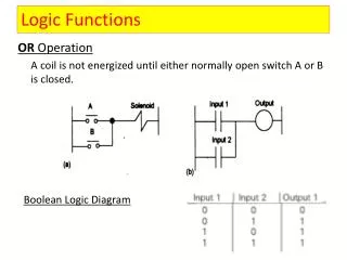
Shuttle Valve (OR Function) • It gives output compressed air signal if any input has compressed air signal. • A shuttle valve is a type of valve which allows fluid to flow through it from one of two sources. Generally a shuttle valve is used in pneumatic systems, although sometimes it might be found in hydraulic systems.
Construction of Shuttle Valve • The basic structure of a shuttle valve is like a tube with three openings; one on each end, and one in the middle. A ball or other blocking valve element moves freely within the tube. • When the pressure is exerted through an opening on one end (port Y)it pushes the ball towards the opposite end (port X). This prevents the fluid from travelling through that opening, but allows it to flow through the middle opening (port Z). • In this way, two different sources can provide pressure without any backflow from one source to the other.
Principle Operation of Shuttle Valve • In pneumatic logic, a shuttle-valve works as an OR gate • If a compressed air signal is applied to input X or input Y, this will produce a signal at output Z. • If there is no signal, there is also no output signal. • If signals are present at both inputs, the signal with the higher pressure reaches the output
Truth Table for Shuttle Valve 1: compressed air is available 0: compressed air is not available OR function gives output compressed air signal if any input has compressed air signal
Circuit with two Shuttle Valves • Shuttle valves can be linked to create additional logic OR conditions . • Operating any one of the three push buttons, results in extending the double acting cylinder.
Practical Task 1 • A flip control is used to empty granular material from a container. This machine can be operated from two different locations using two push button valves. By pressing any one of two pushbutton valves the flap is closed and the granular material is emptied from its container. After releasing the pushbutton valve the flap control is closed again
Solution Description • In the initial position, the piston rod of cylinder1A assumes the retracted end position. The power valve (1V2) is in the left hand switching position. • Step 1-2 If the 3/2 way valve (1S1) or (1S2) is actuated. Pressure is applied at the output of the shuttle valve (1V1). The 5/2 way valve (1V2) reverses. The cylinder travels to its forward end position. If any 3/2 way valve remain actuated, the cylinder remains in the forward end position. • Step 2-3 If the two push buttons (1S1) or (1S2) are released, the power valve (1V2) is no longer pressurized; the valve reverses through the spring. The cylinder travels to its initial position.
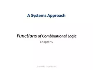
Two Dual Pressure Valve (AND Function) • In certain industrial processes and machines (metal cutting, high capacity presses, forming tools, etc...) where some hazards are incorporated, special measures have to be taken in consideration in order to avoid unexpected accidents. One of these measures is using the Two (dual) Pressure Valve. Using this valve will force the operator to use his two hands in order to operate the machine.
Two Dual Pressure Valve (AND Function) • It gives output compressed air signal if all inputs have compressed air signals applied at the same time. • This valve is very similar to the shuttle valve in shape and construction, but the function and the principle of operation is different. It is used for the logic AND connections.
Two Dual Pressure Valve (AND Function) OPERATION • In pneumatic logic, a two pressure-valve works as an AND gate. • If a compressed air signal is applied to input X and input Y at the same time, this will produce a signal at output Z. • However, if there is no signal, there is also no output signal. • If only one input signal is applied, there will be no output signal .
Two Dual Pressure Valve (AND Function) OPERATION • In case of time differences between the input signals, the signal arriving last reaches the output. • In case of pressure differences between the input signals, the signal with the lower pressure reaches the output. Ports X & Y are pressurized Ports X is pressurized
Truth Table for the Two Dual Pressure Valve 1: compressed air is available 0: compressed air is not available AND function gives output compressed air signal if all inputs have compressed air signals applied at the same time
Equivalent circuit to AND Operation • The two pressure valve circuit is equivalent to the two input signaling devices in series (1S1 and 1S2). One after the other (3/2 way valve, N/C). The signal output is passed all the way through only if both signal elements are operated
Practical Task 2 • In order to maintain a safe operating environment for the forming machine operator, the forming machine has to be operated by two push button valves at the same time. Operation of the two push button valves causes the forming tool of an edge-folding device to fall down rapidly. If both or even just one push button is released, the double acting cylinder (1A) slowly returns to the initial position.
Solution Description • In the initial position, the piston rod of cylinder (1A) assumes the retracted end position. The power valve (1V2) is in the left hand switching position. • Step 1-2 If both 3/2 way valves (1S1) and (1S2) are actuated. Pressure is applied at the output of the two pressure valve (1V1). The 5/2 way valve (1V2) reverses. The piston chamber of cylinder (1A) is supplied with unrestricted compressed air via the one way flow control valve (1V3). The cylinder travels to its forward end position. As the chamber on the piston rod side is rapidly exhausted through the quick exhaust valve (1V4) the cylinder motion is very fast. If both 3/2 way valves remain actuated, the cylinder remains in the forward end position. • Step 2-3 If at least one of the two push buttons (1S1) or (1S2) is released, the power valve (1V2) is no longer pressurized; the valve reverses through the spring. The actuator travels to its initial position under conditions of flow restriction (1V3).